
Suspension Restoration Advice
-
I don't like those "replace the whole suspension solutions", on a Mopar. They are a mark of ignorance. Everybody does it to Chevelles and Mustangs because those cars have crappy suspensions to start with. There are a lot smarter things to spend your money on when resto-modding a Mopar, like the engine.
-
And don’t let a body shop do your suspension.
Basic Street Setup:
-
Stock UCA, offset bushings
-
-1/2 camber, +3 to 3.5 caster, 1/16" toe in
-
Moog rubber bushings on LCA, UCA, strut rod
-
Use new style 2 part Moog strut rod bushing
-
Firm Feel upgraded torsion bars (0.940 or larger)
-
KYB upgraded shocks
-
1973+ A-body disc brake spindles, lower ball joints (same as B-body)
-
Firm Feel level 3 Power Steering box
-
Stock steering linkage
-
Firm Feel 1 1/8 swap bar, poly bushings on bar and bar ends
-
Poly front leaf spring bushings
-
Poly rear bushings
-
NO rear sway bar
-
60 series BFG Radial T/A
-
Todd Rimmer - ’68 Conv.
-
Poly Front End Rebuild
-
PST Polygraphite Front Suspension
-
Added rear bar PST 7/8" rear sway bar
-
340 torsion bars
-
-
They replace the bushings with all new bushings, along with sway bar LCA's and stock sway bar.
-
They get new HD torsion bars. HD rear springs. Front sway bar. They add Moog improved strut rod bushings, and offset UCA bushings. A rear sway bar if you're serious.
Formula S Package
-
What constitutes a Formula S handling package? Mine is a ‘67 convertible with a 340, auto, 8.75 Sure Grip.
-
Stephen Catfish Parker - ’67 Conv.
-
-
In the ‘68 the Formula S package, it had a larger diameter bar in front and heavier springs in the rear with a front sway bar. If the formula S package was ordered the engine would either be the 340 or 383. The bars installed for the 383 would have been larger than the bars used for the 340. The Formula S package was not available from the factory with the 318 or slant six. Even with the Formula S package the disc brakes were an option.
-
-
There may have been a trailer towing package available. If there was then this would have added the heaver rear springs and bars.
-
-
The S package never included disc brakes (at times the 383 did require discs, though). It was a high performance engine (273 from 65-67, 383 from 67-69, 340 from 68-69) with bigger torsion bars, heavier rear springs, front sway bar, and badging. A tach was also included in some years, but I don't think in all.
-
Jim Conner - ’67 Cuda
-
-
Every one of the options was available separately on a plain Barracuda, too (excluding the 383 with only came with the "S" package in 67 and 68, 340 was "S" only in 68, too). My old ‘66 Barracuda (discs, handling package, 273 four barrel, four speed, tach, 150 speedo) was not a Formula S, but it had it all.
-
Jim Lusk
-
-
The basic package came with upgraded heavy duty suspension and the 273 HP engine standard, the 383 was a small increase in price and D-70x14 Firestone Wide Ovals.
-
-
Exterior, the only difference was the Formula S badge on the front fender and if you got the 383 engine then there was a badge on the side above the Formula S badge that said 383.
-
-
Disc brakes, radio, mirrors, sure grip, etc were all extras.
-
Mike Jarvie - ’68 Fastback
-
PS: don't confuse the handling package with the trim options -- these changed from year to year.
-
Max Helm - ’67 Fastback
General Information
-
Top quality suspension components help the balance of a car, especially older models that didn't have the best weight distribution from the factory. Keeping all four wheels pressed to the ground can really improve a car's handling and braking, and being able to firmly plant the rear tires is an obvious way to improve a car's acceleration.
-
-
-
-
There are different ways to update the suspension on your ‘Cuda. You can do a complete rebuild or upgrade to a modern suspension. You can dismantle the suspension repeatedly to replace one or two parts at a time or do it all at once.
Resources
-
A great source for information on improving handling with factory parts is
-
"Performance Handling for Classic Mopars" by Tom Condran (see attached). It also provides background information on suspension theory, and useful guidance for choosing aftermarket parts.
-
-
Petrolicous talks about 1967 Plymouth Barracuda Formula S - Autoblog
-
http://www.autoblog.com/2014/02/12/petrolicous-1967-plymouth-barracuda-formula-s-video/
Removing Suspension
-
You can start dismantling the rear suspension by removing it from the car as an assembly or in pieces. The shackles need to be removed from the springs, the axle housing needs to be removed from the springs, etc. Get the backing plates and the rear shackles off. The nuts holding the front shackles and the nuts holding the U-bolts wouldn't budge, so all you can do is soak them with WD-40. Clean up the shackles with the wire wheel. It's ready for painting.
-
-
Continue disassembling the rear suspension. Remove the nuts from the U-bolts the conventional way or cut the U-bolts with a Dremel tool. Now I've got the axle housing and the springs separated.
-
-
Remove the front brackets from the leaf springs. Soak it with WD-40. There is an inner metal sleeve around the bolt. Just like on the upper control arm bushings. Assuming there is no way to get the hanger off the leaf spring, (use of a Sawzall for that). You'll have to find replacements.
-
Jeff Ramin - ’67 Coupe
-
-
1. The First Step After Securing The Car On Jack Stands And Removing The Wheels Is To Fully Unwind The Torsion Bar Adjustment Screws, Located Under The Lower Control Arm. This Will Relieve The Spring Tension From The Suspension.
-
-
2. Since The Tie Rod Ends Were Worn Out And Will Be Discarded, We Used A Pickle Fork To Separate Them From The Steering Arm. To Use The Fork Successfully, Always Align It So That It Is Working Straight Back Into The Steering Arm. Otherwise The Deflecting Steering Linkage Will Absorb The Force.
-
-
3. After Removing The Wheel Bearing Nut, The Brake Drum Was Pulled Off, Followed By The Backing Plate With The Brake Assembly.
-
-
4. Upper control arm We Used The Pickle Fork Again To Separate The Upper Ball Joint. The Upper Control Arm Was Then Unbolted And Removed.
-
-
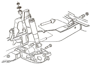
5. Next, The Shock Was Removed. It Anchors To The Lower Control Arm With A Thru Bolt, And A Bayonet Through The Inner Fender Apron.
-
-
7. The Spindle Was Then Unbolted From The Lower Ball Joint/steering Arm. One Of These Bolts In Early A Body Drum Brake Spindles, Threads Directly Into The Spindle. Note The Rounded Head Of This Bolt, And Reinstall It In The Same Position.
-
-
8. Our Handy Pickle Fork Was Employed Once Again, To Quickly Separate The Lower Ball Joint.
-
-
9. At The Rear Anchor Of The Torsion Bar Is A Small Wire Retainer Clip. Remove The Clip To Make Way For Removing The Torsion Bar.
-
-
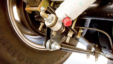
10. The Front Strut Rod Nut Should Always Be Removed First, Then Moved To The Rear Of The Rod. The Tapered Seat At The Rear Of The Bar Keeps The Bar Anchored To Prevent It From Spinning When Removing The Front Lock Nut.
-
-
11. Since We Are Removing The Control Arm, There Is No Need For A Special Tool To Remove The Torsion Bar. Just Remove The Lower Control Arm Pivot Shaft Nut Where The Shaft Goes Through The K Member, And Then Use A Large Pry Bar To Wedge The Lower Control Arm Back. The Torsion Bar Will Slide Back With The Arm, And Out Of The Socket At The Rear
-
-
12. If The Pitman Arm Is Going To Be Replaced, A Large Heavy Duty Puller Will Be Required To Get It Free Of The Steering Box. The Idler Arm Simply Bolts To The K Member, And The Steering Linkage Can Be Removed As An Assembly.
-
-
13. Next, We Stripped The Lower Control Arm, Pushing The Pivot Shaft Out Of The Bushing From The Back. The Bushing Shell Will Remain Fixed To The Shaft, But It Is Easily Removed By Striking It With A Chisel, At 90 Degree Intervals Along Its Length.
-
-
14. We Cleaned And Painted The Arm, And Then Pressed In The Shaft And Fresh Bushing. With A New Bumpstop And The Torsion Bar Adjustment Hardware Installed, It Was Ready To Go Back In.
-
-
15. The Upper Ball Joints Screw Into The Control Arm, And Require A Special Socket To Remove. Be Prepared They Are Tight.
-
-
16. To Remove The Upper Control Arm Bushings, We Use A 1/2 Inch Jackscrew As Shown. The Large Pipe Fitting To The Left Receives The Bushing As It Is Pressed Out, And Is Ground With A Step To Clear The Flange At The Edge Of The Control Arm. The Socket At The Right Pushes Against The Bushing As The Screw Assembly Is Tightened With A 31/44 Inch Drive Impact.
-
Restoring Suspension
-
The process for refurbishing suspension parts is: remove rust with wire wheel, paint w/ POR-15 and then top coat w/ chassis black.
-
-
Before mounting the springs, replace a couple small things, like the exhaust hanger, emergency cable bracket, and axle housing bumpers. Now on to the springs. First thing to do is bolt the front hanger to the spring. Then mount the rear shackle hanger, and slide the rear of the spring onto the shackle. Then it's just a simple matter of lifting the front of the spring into place, and bolting the front hanger to the chassis.
-
Jeff Ramin - ’67 Coupe
Rebuilding Suspension Order
-
Start with the K-member.
-
Then lower control arm bushings on to the lower control arms.
-
Attach lower control arm and struts.
-
Bolt the idler, pitman arm, center link, tie rods, and adjusting sleeves to the K-member and lower ball joints.
-
Install upper ball joints into upper control arm bushings by screwing them in and put cups on them.
-
Use a press to do that.
-
-
Reinstall complete front end assembly.
-
Make sure you just fit everything just tight but not tightened until under full load as bushings will change position ever so slightly but that makes them prone to premature wear.
-
Thomas Liley
Stock Style Front Suspension
-
If you want to keep you stock-style suspension, but make it perform better than stock, the Hotchkis Total Vehicle System (TVS) system might be for you. The Total Vehicle System is the easiest and most effective way to give your Mopar sports car handling. It’s engineered as a tuned performance system, and will reduce body roll, dramatically improve handling, and create incredible driver control for a more enjoyable driving experience. Balanced handling is achieved using geometry corrected upper control arms, adjustable strut rods, adjustable steering rods, front and rear sport sway bars, geometry corrected rear leaf springs, and subframe connectors. www.hotchkis.net
-
-
Performance Suspension Technology is geared towards a factory ride. PST’s parts are precision engineered for durability that meet or exceeds OE standards, and are backed by their Lifetime Limited Warranty. They’ve packaged the components into one convenient Standard Front End Kit for the budget-minded hobbyist. Save time and money by replacing all of the components at once with their Super Front End Kit. Their kits are available with either OE-style rubber bushings or PST’s exclusive Polygraphite bushings. Rubber bushings are best suited for restoration projects where spirited handling isn’t a key objective. Polygraphite bushings are the latest in suspension technology, featuring the lubricating qualities of
-
graphite and virtually zero deflection operation for the best in handling and cornering. www.p-s-t.com
-
-
Rebuilding Front Suspensions With PST – Suspending Dilemma
-
Written by Steve Dulcich on February 1, 2004
-
Hot Rod Network
-
http://www.hotrod.com/articles/mopp-0402-rebuilding-front-suspensions-with-pst/
Upgrade Front Suspension
-
Reilly Motorsports Alterktion front suspension comes as a street/strip unit, or a street/handling kit. The Alterktion system bolts to factory frame rails. The system comes complete from connection to your steering column down to the spindles, and includes a complete 11⁄16-inch sway bar package, custom-valved power steering rack, and hoses that will connect to your factory power steering pump. www.reillymotorsports.com
Aftermarket Upgrades
-
There is a lot more choice in aftermarket handling & brake components then was available 10-15 years ago. But there is also a culture of "overdoing it"-- spending $20K on brand-name bling when you would get 95% of the same result with well under $2000 of carefully chosen parts and DIY work.
-
-
If your interested in better handling and performance than the actual Formula S package, do the following: Add heaver torsion bars, better tie rod ends (C-body), Poly-graphite bushings, a sway bar (mine never had one which also incorporates tabs on the lower control arms), heavier rear springs, and for a step farther, add a FirmFeel power steering box, disc brakes, 11” truck rear drums, as well has an 8 3/4 rear with sure-grip.
-
Rob Robinson - ’68 Fastback
Upgrade Rear Suspension
-
Street-Lynx triangulated four-bar rear suspension kits improve geometry, traction, and handling, while using a much lighter spring and shock to provide excellent ride quality and wheel control. Their system requires no cutting to weld in a single crossbar between the factory frame rails. Coil-overs mounted ahead of the axle eliminate wheel hop normally associated with four-bar systems, and allow stock gas tanks to fit. The lower links bolt into stock leaf spring locations with the included adjustable front mounts, or links can be used in conjunction with standard inboard relocation kits and mounted under the frame rails for increased tire clearance.
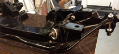
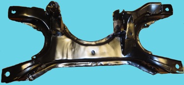
K Member
-
The K-Member supports the engine and front suspension. The 66-70 k-members are the same. Its the 62-65 b-bodies with the later k-members installed that moves the motor back 3".
K Member Restoration
Strengthening on a k-frame
-
It is OK to straighten and repair any damage to the K-frame. Repair welds should be like the factory weld. Simulating resistance welds is a common body repair technique. There's no good way to weld a K when it's still in the car.
Strengthening motor mounts bolt area
-
The worst area is where the motor mounts bolt into the k-frame itself. Double the thickness there or add washers, as the drivers side bolt wears up and the passenger side wears down when the motor torques.
-
-
Try Krasan's site:
http://www.geocities.com/MotorCity/Shop/3978/kmember.html or
http://www.jollyrajr.net/cuda/
Note: Ignore the welds to the motor mount areas. DO NOT do this if you’re running spool mounts. No-no! I had to cut the top welded pieces off! Also, my k-member did not have the idler arm mount boxed or braced like it should have been. I got all my info off the barracuda data resource page.
Raj
Strengthening Joins
-
When I reinforced my K-frame, I put small seam welds on the joins to reduce flex. This also puts the weld further inboard on the lip which is better.
Strengthening steering chuck mounting pad
-
I think the two most important areas to concentrate on are the steering chuck mounting pad: reduce as much side to side movement as possible.
Strengthening lower control arm pivots
-
The lower control arm pivots have been known to crack, and may even rip out under enough stress. I welded on large washers completely around the holes to strengthen it up.
Strengthening sway bar mounts -
The ’67-69 sway bar mounts are pretty lousy, cantilevered out as they are. The rules pretty much allow any method of sway bar mounting. Anyway you come up to improve that will be OK rule wise.
Strengthening idler arm mount
-
The ’67 idler arm mount is bad for the bigger A-body. The idlers give out first so don't worry about that.
Strengthening control arm sockets
-
If you have loose control arm sockets on your K-member, they need to be re-welded/reinforced front and rear. I made a little cardboard template of the area around the rear of such tubes and have used that
several times to cut out repair pieces to be welded in. The same template works for both left and right by flipping it over. When the repair piece is heated from beginning to weld, use a bit of hammer on it to make it conform to the uneven contours of the K-member in that area. The front is easy as pie. Just weld the stock washer onto the K-member. It is very thick and strong and will adequately locate the control arm spindle once you tighten up its nut properly. Together with a rear socket reinforcement you'll have things solidly located. -
K Member Painting
-
Send the K Member to media blasting. Upon arrival, put top coats of satin black and clear coat on the K member. When dry, get the K-member bolted back on. Start the bolts with the K-member balancing on your floor jack. It shouldn’t be too difficult.
-
Jeff Ramin - ’67 Coupe
-
-
Spend a pleasant hour cleaning the K member. Use some purple stuff from O Reilly's in a pretty large container, along with a paint scraper and a few shop rags, plus a trusty HF pressure washer, came out real clean, not near as much a pain as I thought. At least Its clean enough to put in the car. I used the purple stuff to clean mine, blasted and sprayed in 2 part epoxy chassis semi black. Still looks great 2.5 years later.
-
Gerald Drury
-
Paint the K member semi-gloss black.
-
I used SEM suspension and frame paint. Rattle can. I've had good luck with this spray paint in satin black. O'Reilly's carries it.
-
Ron Evans
-
If anyone is looking for a local So Cal shop that does powder coating, call Bob Barnes at Vern's Plating in Gardena (323) 754-3873. They do powder coatings and electro plating (Chrome, Nickel and Copper). Bob Barns is a hot rodder and Mopar owner among his other cars.
-
Mike Jarvie - ‘68 FB
-
I had my K member powder coated in CA and am really glad I did. The coating protects the metal and preserves a piece no longer made and becoming increasingly hard to find.
-
Dr. Bob
-
I've done a few k-members through the years and most fall in the $200 range. I know the rattle can sounds attractive price wise but just remember you're paying for a durable work of art you can be proud of, proper prep work to achieve it, and the convenience of taking it out of the box and installing it on your car. We all know the first time you mate anything to a paint job it's going to get messed up and need touch ups ... but a powder job done right will not and it will last you a lifetime.
-
-
New customers get a 7% labor discount, returning customers get 10% off, and U.S. military / veterans enjoy 12% off the labor through December 31, 2017. Use the Promo Code "PSC10" when you call or write to me for a quote.
-
Leanna ~ The CudaChick
-
I had my powder coating done by Coast Powder Coating in San Clemente, Calif. $150
-
Angel Garrido - ’69 FB
K Member Bolt Restoration
-
If you don't have access to a hot tank, Easy Off oven cleaner and a coin car wash work well to clean them.
-
Jim Lusk
K Member Upgrade Replacement
-
Attach to your K member to the Firm Feel kit.
-
-
For piece placement, the two fully round washers go around the strut rod holes; the two remaining washers, which have flatted sides, go around the LCA tube holes due to placement of the tubes.
-
-
The small triangle went on the top side of the steering box area for reinforcement;
-
The "moon" shaped slice went on the front of the steering box mount above the LCA hole;
-
The triangle with the concave curve on one side went on the open bottom front of the steering box mount area to brace and fill that in;
-
The remaining large triangle went on the open back of the steering box mount (with some shaping using a hammer to get the shape right) to brace that and fill it in.
-
The end result was a solid enclosed mount for the new Firm Feel Stage II steering box.
-
-
Go to a Mopar shop and be sure the LCA tube is welded in straight (if it isn't the alignment will be off). Do all the cleaning prior to the welding to insure the welds would be good: washing off the K member with solvent, wire wheeling off all the rust and loose paint, and wiping it down with alcohol. I also hammered out any major dents. Even with all my cleaning, the k member may become so hot that residual oil and grease inside the k member might catch fire.
-
-
You will need to figured out where the reinforcing pieces go, number them with a sharpie, and put corresponding placement numbers on the K member with arrows. Make up a step by step list of what I you want done. The total cost of having the shop do the k member turned out to be $350.
-
-
Firm Feel charges $375 to do the welding and reinforcing, plus the cost of their kit at $75, plus shipping to and from their shop in Vancouver, WA. All of that would bump the same work to around $550 if Firm Feel did it.
-
Steve
Deciding Which K Member to Use
-
Deciding which K-member to use really depends on which motor mounts you want to use. The 67-72 biscuit or the 73-76 bolt through motor mount.
-
Phil Saran
-
-
The '73 K has a little better designed sway bar and mount, and the motor mounts are less prone to breaking. So if you don't mind changing all that stuff, the '73 is a better design. On my '67 K member, I have already ripped another motor mount in only 14k miles & 5 years.
-
Nathan Nuttall - ’67 Fastback
-
On the build sheet, under line 4, is the frame number.
-
On a ’67 with a 273, the frame number is 12, part #2768548
-
On a ’68 with a 273, 318 or 340 engine, the frame number is 12, part #2883930
-
On a ’69 with a 273, 318 or 340 engine, the frame number is 12, part #2925976
Determining K Member Straightness
-
Measure diagonally. It should measure the same (or very close).
-
Jim Lusk - ’67
Control Arms
-
Worn steering and suspension components cause “play” in the steering system, resulting in unresponsive handling and wandering on the road. Tubular upper control arms can aid handling by giving you more caster/camber adjustment.
-
More caster will tend to have the wheels self straighten more, and makes for a more solid feel on the highway. It also makes low speed steering harder.
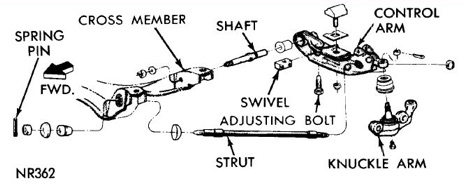
Lower Control Arm (LCA)
-
Originally the lower control arm design was an unboxed U shape, which can be twisted out of shape by a stiff anti-sway bar.
-
-
The LCA pivot arm (PIN) attaches to the K Member. It is a press on bushing with sleeve in the lower arm. The nut tightens it on. Metal on metal. The bushing fits in the control arm. The torsion bar and the strut rod holds it in place.
-
-
The LCA pivot arm attach to the K Member and attaches to the metal directly.
-
Angel Garrido - '69 FB
-
-
It attaches directly. You can use a thick flat washer and a nylon type lock nut.
-
Ron
-
-
There is no bushing. The pivot pin has a slight interference fit in the pivot pin tube. That's why it is critical that it doesn't get tightened until the ride height is set and the car is sitting with weight on the tires. The only bushing is between the pin and the LCA.
-
Jim Lusk
-
Removing Lower Control Arm (LCA)
-
Tear down the right lower control arm; which consists of removing the shock bolt, bumper, pivot stud, and the torsion bar adjusting bolt. Removing the adjusting bolt is far and away the worst part - requires lots of heat from the torch and lots of torque to get that 30 year old rust to concede.
-
Jeff Ramin - ’67 Coupe
-
1. Knock the lower ball joints out. Usually, a hard square whack on the end of the ball joint spindles will
-
do it (remove nut first of course).
2. Remove sway bar and brackets.
3. Remove nuts at both ends of strut rods (roll pin in front end of strut rods). Might need to snap vice grips -
onto strut rods to keep them from turning. Try not to gouge them too badly.
4. Loosen shock absorber bolt.
5. Loosen T bar adjusting bolts (bottom side of LCAs) ALL THE WAY. Penetrating oil on the bolts is usually -
required, and it's a good idea to spritz this on before you do anything.
6. Remove shock absorber bolt.
7. Pull T bar retaining clips at back ends of rear T bar mounts.
8. Remove plastic splash shields on frame.
9. Remove nuts on LCA spindles (part of LCA that inserts in K member).
10. Whack on the ends of the LCA spindles to drive the entire LCA/Tbar assemblies towards the rear of the -
car. Prying between the LCA and the K member helps. Don't mushroom the ends of the LCA spindles
-
with the hammer!
11. When the assembly drops out, slide the LCAs off the front end of the T bars and then pull the T bars -
forward out of the rear mount. Some taps with the BFH can help.
12. Crack open that cold Bud, you'll need it by now.
After you've done this a couple of dozen times, it shouldn't take you more than an hour.
Restoring Lower Control Arm (LCA)
-
With some heat on the rubber bushing, you will be able to pull the pivot stud out of the arm. Don’t worry if you brake the bolt off the rubber stop, as there is a replacement in your front end rebuild kit. Get off the bridge and the bolt that runs through it (the bolt that controls the ride height, or the torsion bar adjuster). It is probably rusted tight. With a lot of heat, a vise and a long wrench, you will be finally able to get it out. Clean up the parts with the wire wheel. The LCA should go in the pile of parts to be media blasted; there are too many nooks and crannies to use the wire wheel on it.
-
Jeff Ramin - ’67 Coupe
-
Press out the pivot shafts or use an old puller tool to remove them. Once the pivot shafts are out, pry out the old rubber bushings with a flathead screwdriver. Keep the original outer bushing shells and inner sleeves for use with the poly bushings.
-
Cleaned-up and paint both lower control arms with chassis black. Lubed the poly bushings, inner sleeves, and outer shells with grease. The new bushings should slide all the way into the LCA outer shells by hand. The inner sleeves and pivot shaft will slide most of the way in. Use a press to completely insert the pivot shafts.
-
Most lower control arms were bare steel dipped in cosmolene just short of the ball joint end. For OEM standards, spray the lower control arm with Cosmoline.
Graveyard Cars -
-
SOME lower control arms were dipped in black paint (semi-flat black). When AO Smith (original manufacturer of control arms for Chrysler) had their cosmolene lines occupied with railroad components they also manufactured, they would run the control arms in black dip.
-
Service replacements were dip painted black paint (semi-flat black).
-
Lower Control Arm (LCA) Stiffening
-
Repair slop in the torsion bar sockets in the LCAs. View this video I put together a couple of years ago. http://youtu.be/Nwes-SP8u4w?list=UUqvjc-8llEE-JKNFYw30-NQ
-
James Lusk
-
Weld the stiffening plates to the lower control arms. I used PST’s LCA rebuild kit. It strengthens the arms and they still look stock. Use vice grips to hold the plates up to the bottom of the arm for welding. When done, ground the welds smooth for a clean appearance.
-
Consider using the Firm-Feel or Mancini lower control arm reinforcement plates. P.S.T also sells them.
Reinstalling Lower Control Arm (LCA)
-
The LCA and strut rod need to be bolted on as an assembly. Remove the t-bar and the LCA, bolt the strut to the LCA, and then replaced the LCA. Then get the right LCA bolted to the K member, and the torsion bar in place. You can't tighten the nut on the front of the strut far enough to expose the hole for the roll pin. You may struggle getting the t-bar dust boots over the end of the t-bar. Resort to using some grease, and it will be a snap after that.
-
-
Only one issue remains. The LCA/bushing/pivot flange are not all snugged up against each other, as one might expect. There is about 1/4" space between the pivot flange and the poly bushing. Pick up a Moog strut rod bushing kit from a parts store. Remove the LCA/strut once again, replace the PST stuff with the Moog parts, bolted it back up, and VOILA! The LCA is now positioned where it's supposed to be. You should be able to get both front wheels on the car in a weekend. Then bolt on the steering knuckle/lower ball joint.
-
Jeff Ramin - ’67 Coupe
-
It’s easiest to attach the strut rod to the LCA and slide them together into their respective holes in the K-member. The pivot shaft and strut rod nuts should only be snug tight. Torque them to specs once the car is at rest. Install the lower ball joint and crank the nut tight until you fit the cotter pin in place.
Lower Control Arm (LCA) Bushings
Poly Bushings
-
I used poly bushings and as a result, the front end is very noisy, even from day 1 with a lot of poly grease used throughout. The only good place for poly bushings is on sway bar end links and rear leaf spring hangars.
-
Nathan Nuttall
-
-
Don't use poly bushings on the LCAs. They are fine for the upper arms and other parts of the front end. They make the car handle great but the ride feels like a buckboard. So you have a choice good ride or good handling.
-
Jim Lusk
-
-
I used a complete polygraphite kit from PST when I reworked the front end. I have never had any trouble or regretted using the poly kit. They claim that the graphite in the polygraphite makes a big difference with noise. Maybe, or maybe I'm just lucky.
-
Michael
-
-
Yes the poly bushings will squeak, but Firm feel has a set of pins with a zerk fitting to grease the bushings. As far as bushings, I would recommend the Prothane bushings.
-
John P.
-
-
I just read a thread on FABO that said you should use adjustable strut rods with poly LCA bushings because they don't locate the arms the same way.
Rubber Bushings
-
Tom Condran liked poly bushings for the sway bar and rear springs and possibly the strut rods - everything else should be rubber.
-
Steve Toth
Lower Control Arm Torsion Bars Adjuster
-
The bolt that adjusts the torsion bar is located inside the lower control arm. It’s what stops the torsion bar from backing out. There is a block and a bolt.
Lower Control Arm Torsion Bars Adjuster Removal
-
The bolt that adjusts the torsion bar must come out of the torsion bar adjuster in order to remove the block. Be sure and raise the car before backing out the torsion bar adjuster bolt. It is a tight fit by design. Soak it with PB Blaster. I've also heard that guys have had luck using hot wax.
-
Jim Lusk
-
If the thread is rusted, try electrolytic rust removal. Leave it in the solution for a day or two. If its still tight, use a 50/50 mix of ATF and acetone as a penetrating oil. It works better than any of the commercial products. Be careful not to let it contact paint, and make sure there are no ignition sources nearby.
Torsion Bars Adjuster Restoration
-
I use a cleaner called "Super Clean". I buy it by the gallon at WalMart in the automotive section. Best general cleaner I've found so far. A paint scraper works well before the spray.
-
Jim Conner
Lower Control Arm (LCA) Ball Joint
Installation
-
On the lower control are is the lower ball joint stud and upper ball joint stud each with a castle nut.
-
-
Position new ball joint stud into tapered hole on lower control arm and tighten supplied nut 70-80 ft. lbs. torque. Install cotter pin on the castle nut.
Castle Nut Torqueing
-
With the upper ball joint castle nut, when installing, you have to torque the nut to 90-100 ft-lbs. It's pretty hard to damage anything there. The only thing that could happen is the nut will strip. I torque them.
-
Nathan Nuttall
-
-
The 1968 Plymouth Service Manual states "Position lower ball joint stud into lower control arm and tighten nut 100 foot-pounds (Fury Models 115 foot-pounds).
Aftermarket Lower Control Arm (LCA) Ball Joint
-
Moog makes the lower ball joints.
-
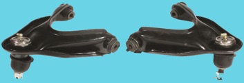
Upper Control Arms
-
The upper control arms were a simple design stamped out of steel. Upper ball joints are screw-in NOT pressed. They aren't part of the lower control arm, they attach to it. They incorporate the steering knuckle and ball joint into one piece.
-
-
One flaw was that the threads in the arm are easily damaged when replacing the upper ball joint, so most original control arms are worn out by now.
Upper Control Arm Ball Joint Removal
-
That upper ball joint is screwed in. You HAVE TO HAVE the special 3/4 drive socket that fits the hex of the joint. Get mine one from Miller Tools it was $36. Put a cheater on a breaker bar to break it loose as it will be tight after many years.
-
-
Use a pipe wrench and a vise to get it off.
-
Jonathan Reck
-
-
Ask if your local O’Reillys Auto Parts store lends out the special ball joint socket. It's huge. I think 3/4" or 1" drive. Apply rust solvent, maybe some heat and go for it!
-
Ed
-
-
I know of a shop in Cypress that can do it, if you want it done. At one time I made a tool that enabled me to change out my A arms. I used a couple of large bolts and an extra long nut from a turnbuckle to spread them apart. Shade tree fix but it worked!
-
Mike J
-
-
Same here. Unscrews right out if not frozen. May want to shoot it with PB Blaster or such and let it soak before trying.
-
Rob Robinson
-
There is a special socket wrench for purchase from PST. Having the proper socket made it easy to unscrew the old, then screw-in the new ball joints.
-
Angel Garrido - ’69 FB
VIDEO: How to Replace Control Arm Bushings
Restoring Upper Control Arms
-
Remove the bushing shells from the UCA. The right tool is a hacksaw. You need to be careful not to cut anything other than the shell. After just a couple minutes of making a nice, even cut through the shell, you can then compress it enough to rotate it, and pull it out of the UCA. It's just slow going. Send the UCA to the media blaster. After, install new bushings in UCA. Take them to a shop to have them pressed in.
-
Jeff Ramin - ’67 Coupe
-
Once they're derusted you can install a reinforcement plate on the lower arms if you wish.
-
Consider installing off-set control arm bushings at this point. It allows more caster in the steering which is needed for radial tires. That is if you have not already done that.
Aftermarket Upper Control Arms
-
There are a lot of options for upper control arms. Some of the aftermarket control arms are adjustable to increase the available caster/camber angles, while others use relocated pivot points to change the front suspension geometry. Stamped replacement upper control arms are available. They can either come as adjustable or nonadjustable.
-
-
For serious performance it is better to purchase a set of fabricated upper arms. The fabricated upper arms are provide more caster and camber than is available from a stock arm. If you want to keep the factory upper control arms, and need more camber, Moog makes an offset bushing to help. The offset bushing locates the center hole of the bushing off center to "move" the control arm farther, in order to gain more camber ability. This makes a car easier to drive and improves its directional stability (reducing its desire to wander). For maximum straight-line acceleration, the best traction is achieved when the camber angle is zero and the tire's tread is flat on the road. Negative camber will improve the grip of the tires when cornering because it places the tire at a better angle to the road.
Off-Set Upper Control Arms
-
The off-set is installed so that the control arm ball joint moves towards the rear of the car. This allows the alignment shop to achieve more caster which is needed for radial tires that have little dynamic caster compared to bias ply tires.
-
The forward control arm bushing off-set is towards the outside and the rear control arm bushing is towards the inside. This will move the ball joint to the rear while keeping the camber adjustment about the same.
-
-
I think this approach is the low cost way to achieve more caster. New off-set control arms from PST or the like may give more caster, but at a much higher cost. I personally don't like “heim” joints on suspension components that have to last a long time on the street. New bushings should last 10-15 years under moderate use.
-
Bob
De-Rusting Control Arms
-
You should electrolytically de-rust the control arms before doing anything else. Then media blast only the black rust that doesn't easily come off with a brush or wire wheel. Use a file to deburr the sharp edges left by the stamping process. Paint does not adhere well to sharp corners/edges.
-
Ken Mayer
Painting Control Arms
-
Depending on the assembly plant, the control arms are black from some plants, and unpainted with Cosmoline coating from others. Some pictures show platinum-style restos with the coated unpainted arms.
-
Rick Erhenberg
-
-
The UCA and LCA are gloss black. I would advise to have them powder coated.
-
Mike Jarvie - ’68 Fastback
-
Paint with a self-etching primer, followed by any primer compatible with your top coat.
-
Ken Mayer
-
Use a self-etching primer. You need to follow that with another primer coat.
-
http://abodymopar.proboards.com/thread/45/suspension-detailing?page=1
-
Rob Robinson - ’68 Fastback
-
Mask the knuckle, the UCA (might have to do some touch up painting, as the ball joining replacement process took some paint off of it), and pinion snubber. Then painted those 3 parts with POR15. That all took 2.5 hours of work. You will be a sweaty, dirty mess by the end of the evening.
-
Jeff Ramin - ’67 Coupe
-
-
I have put a copy of a file "Mopar Chassis Color Chart" in the files section of the site in case anyone wants to save it on their own computer. That sheet has proved to be very reliable for my factory-style restorations.
-
Leanna ~ The CudaChick - ’68 Fastback
Reinstalling Upper Control Arms
-
Be careful reinstalling it or you will strip out the hole in the a-arm.
-
-
Had a little scare when installing the new ball joint saw a little curled up shaving of metal and we both thought we were cross threading it but after removing it we discovered it was from the socket rubbing against the top edge of the circular hole in the upper control arm. Get the UCAs in place. You may struggle, as the bushing fit very tight between the brackets. But some pulling, tugging and light raps with a hammer will get them in place.
-
Jeff Ramin - ’67 Coupe
-
-
The lower joint is bolted to the steering knuckle with 2 bolts. It has the tapered stud into the lower control arm. You have to unbolt it from the steering knuckle first, then unbolt it from the lower control arm. You can use a joint separator pickle fork to get it loose from the control arm. Remember last off is first on.
-
Leave the upper control arm in the car when trying to remove the bj, better to let the car hold it in place than have to find a big enough vise…
Tie Rods
-
There are early and late A-body tie rod ends. The only difference was in the length of the threaded end. I believe the later parts were longer, but it makes no difference.
-
Jim Lusk
-
-
Some of the later model tie rods are a larger diameter tube. The length and threads are the same.
-
Jim Conner
-
There is a difference between an inner and outer tie rod end. One is right hand thread, other is left hand. The inner is the left hand thread. They are different such that as you turn the connecting sleeve, the distance from the balljoint arm and the center link is either increased or decreased, depending on alignment requirements.
-
Jim Conner - ‘6
-
It doesn't really matter as long as each side has one RH thread and one LH thread so when you turn the sleeve, they either go away from each other or toward each other depending which way you turn the sleeve. It affects nothing but the way the alignment is done. All the tie rod is, is a turnbuckle. Turn it around that the direction of rotation changes for lengthening and shortening.
-
Jim Lusk
-
Original Factory Positioning: inners = right threads / outers = left threads
-
For the replacement parts: ES319L is the inner tie rod end, and ES319R is the outer tie rod end.
-
-
I briefly read up on the internet and decided to lightly grease the tie rod sleeve threads, and lightly oil the tie rod stud smooth tapers and threaded ends where the castle nuts go. Some people use grease or anti seize on the tie rod sleeves. We have the grooved tie rod sleeves which I suppose the grooves should face rearward or downward for drainage whenever possible (but the alignment decides which way they face, there isn't much choice).
-
Ed
-
-
I've never put anything on those parts. Perhaps if we lived where stuff rusts it could help, but not so much here.
-
Jim Lusk
Tie Rods Removal and Separation
-
Well, it’s a lot easier to do on the car, with a 3000lb anchor holding it in place. You could hold the link in a vise and use a pickle fork if you’re replacing the tie rod ends and boots anyway. Or there are tie rod end tools that will do it without violence — O’Reilly’s will rent one to you. You will still need a vise.
-
Max Heim - ’69 Conv
-
-
I assume you are taking the tie rod ends out of the center link. Best way is to use a ball joint separator tool (pickle fork) before you remove the center link. If it's already out I usually will run the castle nuts up flush with the end of the tie rod shaft and hit the shaft with a hammer. By running the nut up you won't mushroom the threads on the tie rod shaft. If it's extremely difficult, I will hit the very end of the center link with a hammer, perpendicular to the tie rod shaft. Sometimes that alone will pop the tie rod end out.
-
Try not to go all caveman on it, even if you are not reusing the tie rod ends.
-
Jim Conner
-
-
This is what I used, and I’m pretty sure it worked for everything back when I did my front end.
-
https://www.americanmuscle.biz/AMERICAN_MUSCLE_23000_Pro_Tool_Kit_p/22000.htm
-
Not cheap, but in the end it was well worth it for me.
-
Eric Valentin - ’69 FB
-
-
With this tool. There are two sizes. The larger one works for the pitman arm while the smaller one works for tie rod ends. A 3lb sledge also works.
-
Jim Lusk
-
-
I used the kit from Harbor Freight. The have all the tools needed to get the front end apart and the cost was very reasonable. Then the guy I was working with showed up with a big brass hammer and we hardly used the tools at all except on the joints he couldn't knock apart using Nathan's technique.
-
Steve Toth - ‘6
Aftermarket Tie Rods
-
RockAuto had the Moog ends for about $35 each. Note: Some times you get different ones from different manufacturers. It was an acceptable industry practice to rebox parts into name brand boxes.
-
Jim Conner
-
Tie Rod Ends Rubber Boots
-
A source for replacement rubber boots on the tie rod ends is either RockAuto or Jeg's. They are either Energy Suspension or Prothane.
-
-
The aftermarket ones I've seen are kind of generic. They aren't precisely fitted like the Moog ones that come with the end. They are more like a Chinese cap or a shallow cup. They seem like they would help keep dust out, but not so good for keeping grease in. So don't over grease.
-
Max Heim - ’67 Conv.
Strut Bars
-
On the front end of your strut rod, the bushing may break down.
Non-Adjustable Strut Bars
-
You can buy a set of 2 piece poly bushings that have a metal sleeve that fit over a part of the strut rod. BUT some say poly bushings throw the camber off and you should use adjustable strut rods to alleviate the problem.
-
-
You can get a Moog "improved" two-piece rubber bushing, no modifications required. It’s a good solution at a pretty good price. This is Tom Condran's recommendation. Make sure you put the big washer on the right way -- which looks like the "wrong" way. It should have the cup facing away from the bushing. Again, the big washer goes on with the concave side "out".
-
Max Heim
-
http://www.summitracing.com/parts/mog-k7040/overview/model/barracuda
Adjustable Strut Bars
-
You can upgrade your strut rods with PST’s adjustable strut rods with pivoting Heim joints to provide smoother suspension travel. Suspension and steering response will be much improved. It’s an important upgrade to any torsion bar suspension.
-
-
I would go this direction: Adjustable Strut Rod, 62-76 A-body
-
Classic adj rods have poly bushings. A set of these adjustable rods have a stock appearance for $225. Hotchkis rods don’t look stock but cost closer to $300. PMC style go for a little less money.
-
Stephen ‘Catfish’ Parker
-
-
Company "A" made the mistake of making the poly bushing too thick. Some trim the strut rod bushings to get the LCA to sit in the right place. Obviously, not everyone agrees that this should be done.
-
Michael Mosley
-
-
Yeah, I trimmed mine. Took one of the original ones and trimmed the new poly bushing to match. Also cut off the sleeve to match the thickness of the bushing once it is done. Be prepared to mock it up a couple of times to get it right. When you get it right, the nut will screw on enough to get the rollpin back in. Here is a discussion and pictures about the procedure.
-
but I haven’t had a second of problems. The poly is strong and keeps everything in place.
-
Rob Robinson
-
Consider the QA-1 adjustable strut bar. According to a picture, the LCA end doesn’t look like it will swage or wedge into the LCA like the factory or even the Hotchkis bars. It mounts solidly to the arm like it should.
-
Catfish Parker.
-
-
http://www.summitracing.com/parts/hal-52311?seid=srese1&gclid=COHA6OnI6cICFQ-paQoddUUA5Q
-
-
It has a shoulder that will seat on the LCA on a similar fashion. The jamb nuts on the strut rod have opposing threads on each end and work the same as a tie rod sleeve, turning it one way lengthens it, the other shortens it. Looks like best method is to seat the LCA, adjust the strut rod length, then lock it all down.
-
-
I measured it, since the perspective of a picture can be deceiving (the stock strut rod is a foot farther back on the ground). Stock is 5/8" diameter, QA1 is 7/8" diameter.
-
Michael Mosley
Torsion Bars
-
Originally, the factory offered several sizes of torsion bars for each body line, depending on the use of the car. The softest bars were used in light duty cars (Slant Six–engines), while the strongest bars were for heavy-duty suspension packages, or with optional engines. Factory bars were color coded for size.
-
-
The torsion bar is basically a designed spring that provides great performance from a compact assembly. Having the torsion bars located low in the chassis reduces the center of gravity. The torsion bar is also an unsprung weight. Also the ride height can be adjusted with the Mopar torsion bar design.
-
-
There is a left and a right bar. They have a L or R on them.
-
Torsion bars have a number stamped on the end (i.e. 780R).
-
Torsion bars are 253892 and 253893 (.87" diameter, 110#).
-
Torsion bar 253892R should be on the passenger side, (even numbers = right side).
-
The spring rate of the bar is determined by the fourth power of the bar's diameter. Changing the size, even a little bit, will make a large increase in its spring rate. Note: the spring rate on a 1.180-inch bar is more than three times as great as the spring rate of the .880-inch bar. Measured at the lower ball joint, spring rates for torsion bars are what the wheel sees. On cars with coil springs, the wheel rate is much less than the spring rate due to the geometry of the suspension. A 200 lb/in torsion bar is different than a 200 lb/in coil spring, when comparing wheel rates.
-
In the book "Performance Handling for Classic Mopars" by Tom Condran:
-
-
Torsion bars 0.85” bar would be standard on a 318.
-
Torsion bars 0.87” bar would be HD for a small block (part #2535892 and 893).
-
Torsion bars 0.89" bar from 340, 383 V8 listed for A-body (part #2535894 and 895).
-
Torsion bars 0.92” bar are recommended for big block setups.
-
Torsion bars 0.94” bar would be standard on ‘76 A-body cop cars.
-
Torsion bars 0.99” bar is too stiff for our cars.
-
-
The 2535892 and 893 were originally for 4bbl V8 applications and are .87" diameter - according to the Tom Condran book. And they are the ones commonly referred to as the "340 bars". Those TB's are way to soft anyway. My advice is change TB's to .92 or thicker and see what happens.
-
Dr. Bob
-
Torsion Bar Identifiers
Heavy Duty Suspension
Model Year Engine DiameterLength ID NumberColor Code
67-69 225, 273 .87 35.8892 Right, 893 LeftBlue
69 318.87 35.8892 Right, 893 LeftBlue
68-69 340same as standard suspension
67-69 383same as standard suspension
69 440same as standard suspension
Torsion Bars Problems
-
Torsion bars are very highly stressed suspension members and should not be nicked or damaged.
-
Tim Moeller
-
-
Mixing them up would suddenly create problems, where none existed before, like ride height.
-
John - ’67 Coupe
-
I wouldn't drive it until you correct it. That's dangerous to drive that way.
-
Nathan Nutthall - ’67 FB
Torsion Bars Replacement
-
Replacement bars are available in a range of different spring rates, from drag racing to street use. Only reason to replace them would be to change the spring rate (stiffer for handling).
-
Max Heim - ’67 Conv.
-
-
When picking a bar, select one with a wheel rate that is 1/10 of the front-end weight of the car. [Example a 3,600-pound car with 50 percent of the weight on the front end has a front end weight of 1,800 pounds]. A good starting point for the wheel rate would be 1,800/10, or a 180 lb/in bar. For an A-Body, the .920-inch bar at 150 lb/in is probably the best choice. The next size up is the .990-inch bar at 200 lb/in, which is probably a tad too stiff for most people.
-
-
And a Mopar performance part offering .925" (P5249151) - sounds like you would not want these unless you put a big block in your a-body.
-
-
A-Body bars are shorter than B-Body bars, which makes them stiffer. Also, drag racing torsion bars (with low spring-rates) on street-driven cars will have difficulty controlling a heavy car while cornering. Therefore you wouldn't want to use it for any type of daily driving.
-
-
Hemi torsion bars (for 440 and 426 hemi engine) are heavier, therefore they hold more weight because they wanted the car to be more stable. You would not have gotten Hemi torsion bars on a 383 engine.
-
I cringe when I see Mopars that have the torsion bars removed in favor of coil-over front suspension.
-
Rob Robinson - ’68 Fastback
Torsion Bars Removal
-
You can change the bars fairly easy, but you need a torsion bar removal tool. The surface of the torsion bar is highly stressed, so care must be taken to protect the bars while knocking them out. Don’t use a pipe wrench or locking pliers.
-
Be sure and raise the car before backing out the torsion bar adjuster bolt. It is a tight fit by design.
-
Jim Conner
-
First, jack the front end up and release all tension from the torsion bars by loosening the adjusters. Next, there is a clip on the rear portion of the torsion bars where they connect to the body. You will need to remove that.
-
-
Last, use the torsion bar removal tool or fashion your own to drive the bars out the rear mounting hole. The removal tool is like a clamp that goes around the torsion bar and has the means to use a hammer to drive it out of the socket it seats in. I have seen folks bolt pieces of wood to it in lieu of the real tool. Some folks also have used vise grips - although that method can likely score the torsion bar and make it more likely to fail (not to mention it isn't good for your vise grips).
-
Jonathan Reck
Aftermarket Torsion Bars
-
Replacement bars are available in a range of different spring rates, from drag racing to street use.
-
7/8 torsion bar is 0.875" (actually .870) -- that's the default small block Formula S size, which is good, though some people don't consider that particularly sporting these days. I swapped to .890 (big block standard), but a lot of people go much larger (up to 1.03). Personally, you don't have to make it ride like a truck to get good handling on the street. In the real world of poorly-maintained roads, I like some compliance.
-
Performance Suspension Technologies (PST) offers torsion bars for A, B, and E-Body cars in sizes from .880 to 1.180-inch diameter.
-
Here are the Mopar Performance bars and the Summit Racing Part #’s
-
--------------------------------------------------------------------------------
-
DCC-5249148 Torsion Bar Set, .810 in. OD., `A`Body, Drag Race
-
DCC-5249149 Torsion Bar Set, .870 in. OD., `A`Body, Resto. 340
-
DCC-5249150 Torsion Bar Set, .890 in. OD., `A`Body, Resto. 383
-
DCC-5249151 Torsion Bar Set, .920 in. OD., `A`Body, Perf/Solo Race
-
DCC-5249152 Torsion Bar Set, .990 in. OD., `A`Body, Solo/Road Race
-
DCC-5249153 Torsion Bar Set, 1.040 in. OD., `A`Body, HDSolo/Road/CT
-
DCC-5249154 Torsion Bar Set, 1.090 in. OD., `A`Body, CT Race
-
DCC-5249155 Torsion Bar Set, 1.140 in. OD., `A`Body, CT Race
-
Torsion Bars Painting
-
Not sure powder coat will work long-term on the bars or not. They flex a lot and I would not be surprised if it didn't stay on as a result. Just make sure no powder coat gets on the ends or it will be he'll trying to re-install them. I don't know if the baking in the oven part would be good for them either.
-
Jonathan Reck
Torsion Bars Seals & Clips
-
The car uses 2 seals qnd 2 clips (retainers). One on each torsion bar.
-
The retainers are the circle wire that holds the bar in place. They usually rusty and are almost gone by the time you pull them out of a 30 year old car.
Anti-Sway Bars
-
The factory only installed anti-sway bars as part of an option package, so not all cars were equipped with the proper mounting brackets. These original anti-sway bars were fairly small and had a limited effect on handling.
-
Anti-sway bars work in the same manner as torsion bars, so the stiffness of the bar is determined by the fourth power of the bar’s diameter. A small increase in diameter will change the stiffness of the bar significantly. If your car already has a front sway bar, rear sway bar kits are a good addition. They come with all the mounting hardware and brackets you'll need. An anti-sway bar with stiff bushings gives you stability when you need it, without making the car harsh over bumps.
Aftermarket Anti-Sway Bars
-
The aftermarket has developed brackets and mounts which can be retrofitted to upgrade the ‘Cuda. Both front and rear anti-sway bars are available for A--Body cars. There is a need for larger and stiffer anti-sway bars as tire technology improved. There now is a wide variety of types and sizes of bars.
Sway Bar
-
The purpose of the sway bar is transfer load from the outer wheel to the inner wheel when cornering, to keep the car level. But it is intended to have no effect on normal suspension travel, (i.e. driving over a speed bump). The whole bar (both ends) should just pivot in the frame bushings.
-
Max Heim - ’67 Fastback, ’67 Conv.
-
The Formula S package included a sway bar (and front disc brakes).
-
Robert Wiffen - ’67 Fastback
Restoring Sway Bar
-
Remove the bushings from the sway bar. That can be accomplished with a torch and screwdriver! Derust the sway bar and mounting brackets at the wire wheel.
-
-
New bushings need to be pressed into the brackets. You can use a large pair of pliers to press them in. Get a coat of POR15 on the sway bar, mounting brackets and strut rod pieces. Bolt the thing to the K-member that way, the bracket will be stationary. Put top coats of satin black and clear coat on the sway bar.
-
Jeff Ramin - ’67 Coupe
Aftermarket Sway Bar
-
Aftermarket sway bar install was a breeze. I bought a Hellwig product and am very happy. I had to drill a couple holes in the k but thats all, they are made to fit our cars.
-
Robert Wiffen - ’67 Fastback
-
I have the Firmfeel 1 1/8" sway bar and it also uses link mounting tabs which mount to the shock bolt. The tabs are think steel and nicely done. Never had any problems. Just had it apart for other work an no signs of any issues. Understand and agree that double shear is better, but in this case, single shear seem good enough.
-
Todd Rimmer
-
Summit Racing Equipment carries a full line of Eibach suspension components including coil springs, struts, and sway bars. www.Summitracing.com
Sway Bar Swapping
If you have a 67-72 sway bar and are swapping to the 73-76 style disk brakes
the sway bar will interfere with the caliper. The fix is to swap sides with
the caliper mounting brackets and calipers so the caliper is to the rear. Or,
to use the 73-76 sway bar, lower control arm and k-member.
If you are going to use and after market sway bar then there is no issue.
This IS a confusing topic. Here are the facts:
With a '67-'72 K-member, you can ONLY use the '67-'72 sway bar and lower control arms. The sway bar mounts UNDER the K-member, and the sway bar "arms" are longer than the '73-'76 version and ONLY fit the '67-'72 LCA's.
With a '73-'76 K-member, you can ONLY use the '73-'76 sway bar and lower control arms. The sway bar mounts THROUGH the K-member, and the sway bar "arms" are shorter than the '67-'72 version and ONLY fit the '73-'76 LCA's.
Which brings us to your MP K-member. I will make an educated guess that your sway bar is under the K with the longer "arms", therefore if you go to the '73-'76 single piston discs, you will have to swap the spindles left to right in order to mount the calipers to the rear of the spindle.
If your sway bar goes through the K with the shorter "arms", you should be able to install the spindles in the stock location, i.e., calipers in the front.
If you have an aftermarket sway bar, please disregard all of the above.
Mike K. - ’67 vert & notch
The 73-76 spindles mount the brakes toward the front of the car. The
65-72 K-H disc brake setup mounts to the rear. The 65-72 style swaybar links supposedly interfere with the 73-76 front mounted calipers. I say supposedly cause Phil Saran has 73-76 brakes with his 69 swaybar.
Sway Bar End Links
Poly Bushings
-
Use poly bushings on sway bar end links and rear leaf spring hangars.
-
Nathan Nuttall
Ball Joint
-
The ball joint go on the left. The steering arms face to the rear of the car, and angle inward. If you are mocking up the suspension on the k-member, the steering arms will only match up to the cross link one way.
-
Ron Evans - ’67 Conv.
-
-
Install the lower ball joint on the spindle (knuckle) and you will know which side is which. The ball joint arm points to the rear for the tie rod end.
Shock Absorbers
-
Some people buy the cheapest shocks available. Some buy because of the color. But chassis guys at the track spend a lot of time and money on shock absorbers. Shock absorbers are actually vibration dampers. They don’t support the vehicle's weight. They are designed to ensure that the vibrations transmitted by the spring are reduced. For a correct ride height, the shock should be in the middle of the stroke.
-
Darrell Stephens
-
-
There are adjustable and non-adjustable types of shock absorbers.
-
Both front and rear shock absorbers were part of the Formula S package.
-
-
In ’69, the shocks were given new part numbers. 6 cylinder and 318 V-8 models used the same shocks.
-
Heavy duty shocks, both front and rear, were mandatory if the car came with 340, 383 and 440 engines.
Shock Length
-
A bodies 63-76 Rear shock Lengths are as follows:
-
16.125 extended,
-
10.375 compressed
-
and have 5.75 inches of travel.
Shock Color
-
Front shock absorber mounting, finish should be galvanized.
Aftermarket Shock Absorbers
-
PST carries the Bilstein line of shocks, and has a large range of shock absorbers for Mopar cars. The Bilstein shocks will make your car act like a different vehicle. Tows better too.
-
-
QA1 manufactures some of the best shock absorbers in the industry.
-
For a '68 Barracuda a set of KYB Gas-a-Just performance/handling shocks per Tom Condran's recommendations (Performance Handling for Your Classic Mopar) and they come with a lifetime warranty.
-
Steve Toth
Front End Nose Height
-
If the front end is set lower than the rear the car will handle better at high speed than if it had sat level. On the ‘68 the front is 1 inch lower than the back, as was set up from the factory.
-
Darrell Stephens
Adjusting Front Ride Height
-
On these cars the front end height is controlled by a large bolt under each lower control arm. The factory service manual has a specific procedure for setting this, but assuming the alignment is reasonably close to start with, lowering each side one or two turns (both sides EXACTLY the same amount, of course) won't hurt. Bounce each front corner a couple times after each attempt, or it won't seem to be making any difference.
-
Max Helm - ‘67 Fastback
-
-
Get underneath the front and let down the adjusters a turn or two to lower the front end of the car a bit.
-
Nathan Nuttall - ’67 Fastback
-
-
You can lower the front by turning the torsion bar adjustment bolts. There is a 3/4" bolt under the lower control arm (LCA) that you unscrew to lower car. But you must go slowly as the torsion bar needs to settle. Unscrew 4 turns per side, drive around the block and re-measure. Just keep careful notes as to how many turns of the socket you do per side. Once you like the "look" take it to be aligned and you are good to go.
-
Dr. Bob Breed
-
-
Note: Changing front ride height may affect front end alignment.
-
Yes, adjusting the height changes the camber, which, taken to extremes, will wear out one edge of the front tire (for example, lowering will tend to wear the inner edge). It's a matter of degree -- a couple of turns may not be critical. Raising is more problematic than lowering, since it rapidly gets into positive camber, which is undesirable, especially for radial tires.
-
Taller tires or 15" wheels and tires in the back will raise it some.
-
Ridge Hard
Adjustable Upper Control Arms
-
To compensate for lowered ‘Cuda height, Adjustable Control Arms can provide better adjustment capabilities over stock or just easier adjustment. They will help make it easier to adjust the driver's side control arm via the eccentric bolts. Changing front ride height may affect front end alignment.
After-Market Adjustable Upper Control Arms
-
RMS makes adjustable tubular arms. They are easy to adjust, but must be pulled off the frame mounts to adjust.
-
Hotchkis makes them but almost 2x price.
-
Mancini makes a Single adjustable designs for reduced failure points. Magnum Force also makes them.
-
-
Use the Heim joint for less drag and more adjustability and it does have poly bushing option. They will last longer.
-
-
Running 73 spindles , 69 k frame , stock struts , stock LCA .
-
-
‘67 is same as ‘69 for all these parts except for k with its ‘67 single sheer idler arm.
-
Todd Rimmer
-
My general recommendation has been to simply use the stock UCA with the Moog offset bushings. I've had good luck with these on street cars. If you can get the desired camber/caster with this setup it is strong but a little heavier than the tubular arms.
-
Todd Rimmer
-
You might give Peter Bergman a call. He takes time to talk to people, and answer their questions. He listens and suggests options.
-
Ron Evans - ‘67 Coupe
Bushings Kits
-
Kits will work for an occasional driver. It will take a little research and comparison shopping. For best results you really want the "best of breed" components.
-
-
On my first rebuild I used Kantner's kit, but a better choice would include the Moog offset upper control arm bushings, and the Moog improved design strut rod bushing. Then if you have a sway bar, you would want polyurethane bushings for that. Moog offers two versions of the upper control arm bushing, and the strut rod bushing. One is the standard replacement Moog parts and the other an improved Moog part. Moog offset bushings help with getting your ‘Cuda to align well.
-
Max Heim - ’67 Fastback
-
-
I heartily agree with Max. The Moog offset bushings alone are such a nice improvement, that I can't imagine building a front suspension without them. So I usually purchase the parts separately through RockAuto.
-
Nathan Nuttall - ’67 Fastback
-
-
I used a kit from PST and was happy, am happy still and you can get a 10% discount through FABO.
-
Robert Wiffen - ‘67-440 Fastback
-
-
Bought all my front end rebuild components from PST, not familiar with Springs-N-Things.
-
Tim Moller - ’69 Conv.
-
-
I just have to say that I've used PST kits on some of my cars and locally sourced Moog branded components on others. So far the components have been identical right down to the same tiny numbers molded into the rubber.
-
Bill Parker
-
Use poly bushings on sway bar end links and rear leaf spring hangars.
-
Nathan Nuttall
Boots & Clips
-
You have boots and clips on your car right now, presumably. The question becomes, do you want new ones instead of 40-year-old ones caked with dirt and grease. You’ll want to look underneath and ascertain if your boots are in good shape, so you can order a replacement if one is torn, for instance.
-
-
Mancini Racing has boots/clips for $40. About the same price at MrMoparts and Summit. Good article on torsion bars:
Front End Alignment
-
Our older cars have a camber, caster and toe in adjustment.
-
The original alignment specs are for bias ply tires. If you have radial tires use Aspen alignment specs.
-
Daty Rogers - ‘67 Conv.
Alignment Specs
-
Take your car to the alignment shop and remembered that for best performance, you really should use specifications from the Mopar greats such as Tom Condran and Rick Ehrenberg. But where do you find that stuff? The archives from the BOG of course.
-
Ron Evans - ’67 Conv.
-
1967 Plymouth Barracuda Alignment Specs
-
Factory Custom
-
Ride Height 1-3/8" [± 1/8"] 7/8" (1/2" drop)
-
Camber Left + 1/2o [± 1/4o] - 1/2 degrees (both sides)
-
Right + 1/4o [± 1/4o]
-
Caster 0 to -1 degrees + 3 to +4 degrees
-
Toe-in 1/8" [± 1/32"] 1/16"
-
Modifications to this car:
• Reinforced later-style K-frame (68-72) with improved idler arm
• Moog K7103 offset upper control arm bushings (increase positive caster) -
• 0.890" torsion bars (“big block”)
-
-
Rick Ehrenberg of Mopar Action did a story on this subject in the Oct. 05 issue. Basically, you want some positive caster and you always want some negative camber for quicker response and a skosh of toe-in. He printed a chart on page 97 which is below:
-
-
Driving style camber caster toe-in
-
Granny - .25 +1.5 1/16 to 1/8
-
Typ perf street - .5 +2.5 "
-
Max perf street - .75 to 1.0 +2.5 to 3.5 "
-
Track-autoX -2.0 to 3.0 +3.0 to 4.0 0 to 1/16
-
Drag Racing 0 +1.5 to 2.0 0 to 1/16
-
-
These are updated specs for Mopars with radial tires. Max is short for maximum.
-
Between this and Condran's recommendations, you should be good.
-
-
P.S. I think you want a little nose down attitude. It looks better and it's more aerodynamic for better fuel mileage.
-
-
P.P.S. With the stock upper control arm bushings, most times you'll have to settle for any positive caster you can get. That's what happened with the ‘68 when aligned in CA. The guy was able to just get
-
it into the positive zone. Course he was dealing with the FTJ factor.
-
Dennis
Ride Height
-
The factory measure for ride height is not between the body and the ground. It is between the inner pivot of the lower control arm, and a point on the steering knuckle. This insures that the suspension is at the correct height regardless of body panel condition or tire size. The process is described in the FSM.
-
If the car appears to sit level side- to-side and front-to-back, it should be fine. Getting random measurements with different tire and wheel sizes will not be helpful.
Max Heim - ‘67 Fastback, ‘67 Conv. -
On the lower arm of the front suspension, you will measure the distance , between the inner point of the lower arm (that is below the inner rubber bushing, to the floor that dimension is called "A" and should be greater always to the next dimension that you will measure).
-
The second dimension , that you will measure is the distance from the middle of the steering knuckle of the lower arm (that is from the lower edge of the steering knuckle, to the floor, and is called "B" and should be smaller than "A").
-
"A" minus "B" , for all the 67,68 and 69 Barracudas should be :
-
1 3/8" (That is one inch and 3/8" of an inch). 1.375" = 34.2 mm.
-
The allowable difference from side to side is: 1/8" of an inch = 3.175 mm.
-
For the Dart they ask for a dimension of 2-1/8"
-
The height is easily adjusted in these torsion bar Chryslers, by turning the bolt that is in the lower arm (close to the inner bushing) in or out .
-
Both manuals recommend, bouncing the car 4 or 5 times, before measuring.
Javier
Steering and Suspension Link
-
Also might try calling A&M HighTechAuto
-
They might have the 610-104 studs (Rear Only, LH thread for 10 or 11" )
-
Go to their steering and suspension link on their home page.
-
Or just email, Bill Allphin: sales@amhightechauto.com
Parts
-
You might want to contact Dr. Diff over on http://www.moparts.com he builds rear ends and suspensions out of his shop in Montana and is a wealth of information.
-
Phil Saran
Leaf Springs and Hangers
-
Leaf springs come in several different styles. There are mono-leaf springs, (one plate of spring steel). These are usually thick in the middle and get thinner toward the ends. Multi-leaf springs consist of several leaf springs of varying lengths, stacked on top of each other. The spring rate will set the tone for the rest of the suspension setup. This means how fast the car reacts to driver input (throttle, brake, turn in, etc). Spring rate dictates how stiff the car's ride is.
-
-
The Chrysler biased design of the extra leaf on the passenger side helped control the axle on high-powered cars.
Leaf Springs Code
-
Rear leafs right and Left side have as code 132.
-
Leaf Springs Leaves
-
Model YearType of Suspension EngineNumber of Leaves
-
67-69Standard 2255
-
67-69Heavy Duty 2256
-
67 Standard 2734 1/2
-
67 Heavy Duty 2736
-
67 Standard 2736
-
68-69Standard 3184 1/2
-
68-69Heavy Duty 3186
-
68-69Standard 3406
-
67-69Standard 3836
-
69 Standard 4406
-
Leaf Springs Sag
-
Rear springs can and will lose their arch. Any new spring would probably raise it a bit. It's hard to predict how much -- everyone's car is different.
Leaf Springs Removal
-
Remove the front brackets from the leaf springs. Soak it with WD-40. There is an inner metal sleeve around the bolt. Just like on the upper control arm bushings. Assuming there is no way to get the hanger off the leaf spring, (use of a Sawzall for that). You'll have to find replacements.
-
Jeff Ramin - ’67 Coupe
-
-
To remove leaf bring nuts you may have to heat them first and then use an impact gun. Note the nut will be hot so watch your toes.
-
Graveyard Cars
Aftermarket Leaf Spring Manufacturers
-
Mopar Performance offers a few different leaf spring packages including the XHD (extra heavy duty) bolt in springs for street performance, Oval Track has springs for track days, and Super Stock have springs for drag racing which require a longer spring hanger. Hotchkis Sport Suspension makes what they call a geometry correcting leaf spring that reduces roll steer. The kit features a bolt-in relocation bracket for the front of the spring, paired up with 160-lb/in leaf springs to improve handling performance and balance. This spring is designed to lower the car approximately 1-inch which reduces the vehicle's center of gravity.
-
-
Controlling the lateral movement of the rear end under hard cornering can be accomplished by installing a Panhard rod or Watt's link.
-
I run the heavy duty EPSO springs with no added height increase and the stance is where I want it.
-
Rob Robinson - ‘68 Fastback
Restoring Leaf Springs Parts
-
The only restoration necessary is a little painting: top coating of shock plates/spring hangers, and POR on the U bolts and new shackles.
Leaf Springs Bushings
-
There are two types: rubber and urethane. The rubber ones are the traditional version and the polyurethane's are the upgrade -- they're a lot less squeaky.
-
Leanna ~ The CudaChick
-
-
Use poly bushings on sway bar end links and rear leaf spring hangars. People say that rear leaf spring bushings are one of the best places to use polyurethane because there is no downside to it.
-
Nathan Nuttall - ’67 Fastback
Replacement leaf spring bushings
-
Eaton Detroit Springs
-
-
They have the correct bushings for my 383s.
-
Gerald Drury
-
-
Autozone, Jegs, Summit, etc. list various generic 61-76 A-body kits. Moog has the shackle bushings for $9.99 per side for the kit. Jeg's has the best price for a complete kit.
-
Jim Conner - ’68
Troubleshooting
-
I have a strange issue with my Barracuda where the car will bounce diagonally right front to left rear when going over bumps. This diagonal bounce happens when going straight, or any direction. When I go over a large, even bump in the freeway, like going over a bridge where the level changes quite a bit, is when it is more noticeable. It also doesn't seem to bump steer very much. It mostly steers straight, it just bounces a lot more on the right front than it does on the left front.
-
-
Perhaps something may be bent or maybe a wrong leaf spring on one side (stranger things have happened). If the rear axle were pointing a little in the wrong direction, I can see how that might cause what I am experiencing once the front wheels lose some of their traction from a bounce. This could be from the rear axle or wheel bottoming out on the left side only. The car does have those overload springs on the leafs. I wonder if that might be part of the problem.
-
-
I have replaced the T-bars & shocks but nothing so far has changed it. I also rebuilt the front end with new joints & bushings etc. I am thinking it may be time to check the LCA mounts if they are loose.
-
Nathan Nuttall - ’67 Fastback
Rear Trailing Arms ?
-
I had a similar problem with my Corvette. When you hit a bump the car wanted to dance sideways. It felt like the front end was darting. I rebuilt the front end and still had the same problem. Turns out the problem was a bearing in the rear trailing arms. You might want to check the rear suspension and make sure everything is in order.
-
Jim C.
Shock Absorbers ?
-
When you bounce the fenders from the top (i.e., do the standard shock test), so the right and left respond the same?
-
Ron Evans - ’67 Coupe
Suspension ?
-
A trick is to take a string while car is on the ground hold string from front of front tire to rear of rear tire and see if car and suspension is straight. I do this at the track after hard rubbing of paint and wheels, to see if anything has changed. Same size tires front and rear. Something must be lose, bent or broke to upset the car that much.
-
Ridge
Sway Bar ?
-
If you have a sway bar, check to see if the end links are tight.
-
Ron Evans - ’67 Coupe