
General Information
Manual Steering
Manual Steering Boxes
-
The manual box (in good condition) gives great road feel on the highway. Parallel parking can be a bit of a chore, depending on what size of gumballs you're running. But the big steering wheel gives you plenty of leverage. Plus, the manual box helps itself out by being aluminum instead of iron, and avoiding the heavy pump and reservoir. Many people ditch the power steering for manual (less weight and take less room for headers).
-
-
As far as manual steering boxes, A, B, E, F, M and J were all interchangeable (almost "the same", but there were 3 different ratios).
Restoring Steering Boxes
-
Read the Factory Service Manual to learn about the steering gear box. Degrease the steering box. Use a bucket of Simple Green and some wire brushes. It is very messy - oil/grease getting splattered all over the place.
-
-
Checked the fluid level. If one of the seals is leaking, you will find out when you fill it back up. If it is leaking, just fill it with axle grease, as opposed to taking it apart to replace a seal. Fill the steering box with oil and exercised it.
-
Jeff Ramin - ’67 Coupe
Steering Linkage
-
You can improve the steering linkage to enhance the feel and precision of steering. If you have a manual steering box, you can change to a faster ratio box using either a 16:1 gear set or a 20:1 gear set. These quick ratio gear sets can be hard to find. The quick ratio steering box will increase the steering effort, so be careful if you have a nose-heavy car and wide tires.
-
-
Power steering boxes can be rebuilt and tuned up by the guys at Firm Feel to provide more road feedback.
Reinstalling Steering Linkage
-
Bolt the steering arms that came with my rebuild kit to the steering knuckles. Bolt on the steering knuckle/lower ball joint. Install the left front shock when bolting on the steering knuckle. Remove the wheel, and bolt the shock in place.
-
Jeff Ramin - ’67 Coupe
Sector Steering Support Kit
-
Someone did the sector support and the roller bearing for the idler and that the steering was greatly improved and super smooth. Firm Feel only sells stuff that works, it is not about marketing or gimmicks.
-
Michael Mosley - ’68 Coupe
-
-
Mopar Action article on sector support kit (steering):
Power Steering
-
It's a fact of life that the older you get, the harder these old cars with manual steering are to maneuver. Get power steering.
-
Jim Conner
Power Steering Boxes
-
The ‘67 and ‘68 steering boxes are the same.
-
-
You don't have to re-invent the wheel here. Get a used power steering box out of an A body or B or C, get someone (Firm Feel for example) to rebuild it, get appropriate brackets for a Saginaw pump, use the Flaming River U joint and go. It is easy to do (relatively) and should be as inexpensive as you can get. There are other options out there but costs are a bit high.
-
Bob
Power Steering Gears
-
There are TWO main power steering gears - small sector shaft and large sector shaft.
-
•Small shaft (early A-body) is what originally came on our cars and uses a smaller splined pitman arm. That will be a bolt in with you current center link.
-
•Large shaft ( B, C, E ,etc.) uses what I refer to as an larger splined pitman arm that mounts differently than the smaller pitman. This requires a lot more parts to work on our cars. Larger ones are easier to find but finding a later V8 center link is difficult.
-
•A company like Firm Feel will have both types - you just may get hit with a core charge since you don’t have one to exchange. They also rebuild them with different firmness from very easy, to quite stiff. They are sold in “Stages”.
-
Rob Robinson
-
-
I strongly agree! I have a stage 3 Firm Feel modified box in my Barracuda and I love it!
-
Dr. Bob Breed - ’67 Cuda
Power Steering Boxes Restoration
-
Firm Feel can restore your box. Send it to them and they will completely go over it. They offer 3 stages for restoration. Stage 1 for racing, stage 2 for light driving. But for our cars, they recommend a Stage 3 modification. Cost is $379.
-
Angel Garrido - ’69 FB
Aftermarket Power Steering Boxes
-
Borgeson makes a fine steering box. The Borgeson Power steering box works with both stock manifolds and headers, TTi headers.
-
Dr. Bob Breed
-
-
Call Peter Bergman in NY. 631-423-1517 or 516-384-6438 He can provide all the info you need to know about the Borgeson box, plus he is a great guy, a MOPAR guy, to talk to.
-
Dr. Bob Breed
-
-
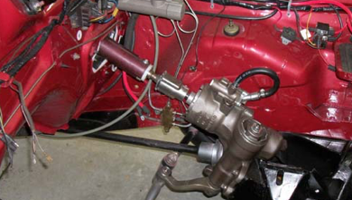
With the headers, the coupler between the new box and the steering column hit the headers, so we ended up putting shims to clear the header. With the Bouchillon PS pump mounting bracket, the pulleys just never seemed to line up and there was a major clearance problem for the PS pump. It sat right on the K frame to the point where we would have to notch the K frame (not good) to get it to work for the hoses. Soooo I decided to take the plunge and buy the March bracket for the Saginaw pump. Everything fell into place with plenty of clearance.
-
Dave Dalmas - ’67 FB
Power Steering Links
-
There's no such thing as a V8 center link ‘67-later. There are, however, two different links that cover groups of years (‘67-’72 and ‘73-’76). The only k-member that cannot use both links is the ‘67 due to the one-year idler arm.
-
Jim Lusk
Power Steering Shafts
-
The ‘67 and ‘68 steering shafts are different lengths. The steering shafts are also shorter for the Power steering.
-
-
Call Firm Feel in Oregon for what fits what.
-
-
To replace, you may have to either change the column, or in one case, collapse the actual shaft. It is two-piece starting in ‘67, and has a plastic "shear pin." I found that the shaft has two sets of holes, so all the shafts may be the same, just collapse it to align the second set of holes. That will also require some cutting on the end of the outer column (the "shroud"). It was a fairly simple job. If you try that, use an appropriate material for the new shear pin, or you'll have a spear.
-
Michael Mann
-
-
There are a number of ways to fit stock steering to a power steering box. I like the Flaming River U joints. Good directions on install but you still have to remover column.
-
-
Be careful about installing a used box since install is tough especially with headers.
-
-
You will like it a lot, faster steering, ease of parking, etc.
-
Dr. Bob Breed - ’67 Cuda
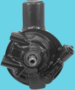
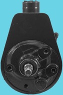
Power Steering Pumps
-
There were two types of poser steering pumps made for Mopar: Federal and Saginaw
-
Half of the bracket is different for the two. The pulleys are different and not interchangeable.
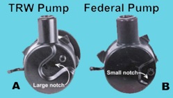
Federal Pumps
-
Federal pumps came stock on ‘67 and ‘68 A bodies. They are junk.
-
Rob Robinson
-
Federal pulleys are hard to swap and not available aftermarket.
-
Saginaw Pumps
-
Saginaw pulleys are an easy fit and can be bought new.
-
The Saginaw pump is a superior unit and having much better parts interchangeability and availability, even though it is not original to 67-69.
-
Max Heim - ’67 Fastback, ’67 Convertible
-
I would encourage you to get a Saginaw pump.
-
Rob Robinson
-
Rebuilt Power Steering Pumps
-
Whatever your choice is, have it rebuilt. Firm Feel could most likely tell you if a particular pump will work with whatever unit you decide on. Any company that makes hydraulic lines could make you something that would work.
-
Rob Robinson
Aftermarket Pumps
-
Check out the Mopar mags. You should be able to get all you need from the vendors listed in Mopar Collectors Guide, Mopar Muscle or some of the large suppliers of parts for our cars such as Classic Industries
-
Dr. Bob
-
-
When I switched from a Federal to a Saginaw, I posted a Parts Wanted ad for the brackets on FABO, and got a reply almost immediately.
-
Max Heim - ’67 Fastback, ’67 Convertible
-
-
You can buy a new Saginaw pump and pulley from Classic Industries and others.
Power Steering Pressure Hose
Replacement FEDERAL power steering pump hoses
-
Part number 352740 ( Gates - expensive)
-
Part number 70333 ( Masterpro - inexpensive). Summit even stocks it!
Power Steering Adjustable Tension Rod Tool
-
The adjustable tension rod is used to provide additional tension to tighten the power steering belt on the power steering pump.
-
-
You can find them advertised as a 'universal' tension rod that had a heimed joint on one end and a flat mounting tab on the other end. March Pulleys has some examples (alternator tension rods mostly); but they are very expensive.
Power Steering Pump Paint
-
The power steering pumps from the factory were a black semi-gloss paint.
-
Phil Saran
-
-
When I painted my power steering pump, I used a self-etching primer. I did not know, however, that I needed to follow that with another primer coat.
-
http://abodymopar.proboards.com/thread/45/suspension-detailing?page=1
-
Rob Robinson - ’68 Fastback
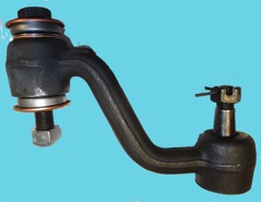
Power Steering Idler Arms
-
There are 4 idler arms listed for 2nd gen A-body.
-
1967 (bayonet style)
-
1968-72 small block
-
1968-72 big block
-
1973-up
-
The idler arms on the ‘67 and ‘68 are different. They changed the idler arm because the bayonet mount used up through ‘67 was prone to wallow out if the nut ever got the slightest bit loose, basically ruining the K-member. But the steering geometry is otherwise identical.
-
Max Heim - ’67 Fastback
Idler Arm
-
There are two different types. A '68-'72 and '73 up. One mounts under the center link, the other mounts over.
-
Michael Mosley
-
-
-
One has two typical joints with a castle nut on each end. The other has the typical joint with castle nut on the steering link. The ‘68 and up cars have the bolt through arrangement on the K-frame.
Aftermarket Idler Arm ‘67 Cuda
-
PST Suspension has the ‘67 style arm for $89.
-
-
I bought mine though a place called Rare Parts in Stockton, CA. Their phone number is 209-948-6005.
-
Dave
Replacement
-
If you have the correct pitman for the box (small spline or big), then the idler and center link have to match the pitman arm. So, it is possible to have a '68 K member with a '75 steering linkage, or, as is in my case, a '75 K member, '68 steering arms, '68 center link, and '68 C-body tie rod ends and sleeves.
-
Michael Mosley
-
-
It would probably be cheaper to buy a ‘68-72 K-member and idler arm than to replace a ‘67 idler alone....or add the top metal tab that the '68-up k-members have, to the '67 K., and use the '68-up arm.
-
Alan
-
-
But you'd have to cut off the whole ‘67 tab and weld on both parts of the ‘68. They aren't the same shape, thickness or location. The main problem with that approach is getting the location and alignment perfect. It's not one of those things where you can afford to be 1/16" and 2º off perfect.
-
-
I would consider trying to fab something up or getting a later tab because you are right, the ‘67 tab is roughly in the center of the ‘68-up tab. I don't think the location is quite as critical as you think, but I'd be sure to have the k-member out and cleaned up before an attempt and I would try to be very precise with the location.
-
Jim Lusk
Steering Link
-
Also might try calling A&M HighTechAuto
-
Go to their steering and suspension link on their home page.
-
Or just email, Bill Allphin: sales@amhightechauto.com
Steering Column
Steering Shaft
-
The collapsible column shaft is 2 pieces, one slid inside the other with plastic sheer pins holding it together. Those should only sheer in collision. And no matter how bad one is wrecked, the steering wheel still would steer the front wheels as much as body damage would allow.
Steering Column Removal
-
To remove start with 3 or 4 bolts under dash.
-
Remove bolts from under carpeting.
-
Detach from steering box.
-
There is a small pinion at base of shaft. Rotate shaft and use a square hole punch the side of hold and punch opt pinion. Shaft should now come out.
-
Alan Erland
-
-
For our A body, all you do is remove the closeout panel under the column and then under the dash there are 3 bolts that hold the column to a structural member. It will also help some to loosen the 4 bolts at the firewall.
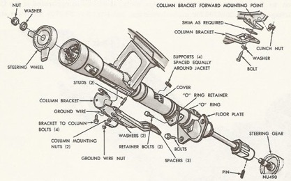
Steering Column Disassembly
-
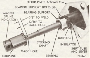
Special tools are needed, as per the ‘68 Repair Manual. The manual states that a steering shaft remover tool is needed to remove the steering shaft from the upper bearing. Most everything comes apart from the top. The upper bearing comes out with the shaft.
For removing the upper bearing.
-
When you get the shaft out, turn the shaft bottom side up, put on a solid surface, put an open end wrench around the shaft, 9/16” as I remember, and tap the wrench with a hammer to drive the bearing off the shaft. Works better with a helper. Expanding split ring pliers are about the only special tool.
-
Jim Conner - ’67 Cuda
Steering Column Restoration
-
Derust / degrease / clean all the brackets and bolts associated with the column. Paint the bracket that mounts to the firewall with POR15.
-
-
Clean up the bright metal on the steering column (the directional lever and the steering wheel spokes). Remove light surface rust with steel wool and WD-40. Some of the crevices in the steering wheel spokes take quite a bit of time.
-
-
Mask off the steering column so it is ready for painting. Paint the steering column and the brackets that hold it to the firewall and dash with POR and a flat black top coat.
-
Jeff Ramin - ’67 Coupe
Re-assembly
-
Apply a thin coat of Multi-Purpose Grease to all friction services.
-
-
Slide shaft in to column.
-
Coat spring washer with grease and install on lower hub of gearshift housing.
-
Put on gearshift housing on to column jacket.
-
Make sure upper key of shaft goes into gearshift housing slot.
-
Tighten shift tube lock screw with Allen wrench.
-
Put on lower snap ring onto lower groove of steering shaft.
-
The only problem you will have is with reassembly of the two odd-shaped bolts that come up through the center plate. Mine was a column shift and I changed it over to a floor shift. I cut off the indicator and the shifter collar and fiberglassed the holes. I didn't have any special tools. I took pictures as I disassembled. Be careful and gentle with the turn signal assembly, the plastic is probably brittle. If you are careful and patient you won't have any problem. Mine is more complicated than yours because the lower collar on mine had to rotate for the shifter. I'll look to see if I have any diagrams or documents.
-
Jim Conner - ’67 Cuda
Non-Disassembly
-
You do not have to disassemble to just paint the collar. No special tools are needed. You just have to be REAL careful and pay close attention as you disassemble everything. Don't be afraid to dive in and redo it, just pay close attention as you go.
-
Stephen 'Catfish' Parker - '67 Conv.
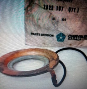
Steering Coupling
-
The box coupling has lengthwise travel/movement inside for 2 reasons. Mostly because unibodies flex and allows for wider build tolerances too.
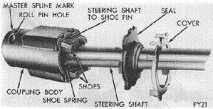
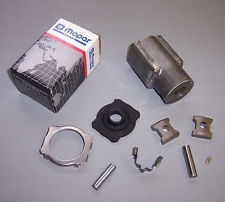
ASSEMBLY OF STEERING SHAFT COUPLING
-
Steering Coupler Package (Rebuild Kit) - Chrysler Part #4443436AC
-
-
1. Fill coupling body to 1/2" from top with automotive multi-purpose grease. The grease recommended during assembly procedure is NLGI grade 2 E.P. or multi-mileage lubricant, Part Number 2525035.
-
2. Place seal cover and seal on steering shaft.
-
3. Press the shoe pin into the steering shaft so that it projects an equal distance on each side of the steering shaft.
-
4. Place spring on side of shaft, straddling the shoe pin.
-
5. Place shoes on pin ends, flat side of shoes to be toward spring engaging tangs on spring.
-
6. Squeeze shoes together compressing spring and push assembly into coupling body.
-
7. If the body has dowel pin hole near cover, drive in a new pin P/N 9431620 flush to the outer surface.
-
8. Position seal and cover on the body and crimp cover tangs over projections on body securely with a large channel lock pliers so you can "squeeze" tabs from each side at same time. Or clamp cover and body together and punch the tangs individually.
Aftermarket Steering Coupling Kit
-
If you put in a new manifold, let’s say a Ram truck manifolds, and it gets in the way, consider exchanging it for a newer u-joint type coupling.
-
Jim Conner - ’67 Cuda
-
-
You can buy a u-joint from Flaming River.
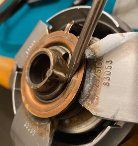
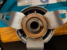
Steering Coupling Retaining Clamp
-
Mopar steering coupler clamp Part #2996935; This factory designed piece was required to be installed as per Mopar Dodge Chrysler Plymouth Technical Service Bulletin No. D69-19-4 in all vehicles using the 3 inch overall length steering coupler whenever the steering column or steering box was "disturbed for any reason." This was due to the tendency and frequency of the crimped on steering coupler seal cover to come loose whenever the cover was crimped on outside the factory. Many cars were coming back to the dealership for service and the technicians were having a difficult time securing the seal cover to coupler due to the small retaining tabs. This created an unsafe condition and allowed the seal to come loose and grit and water to enter the coupler. This ingenious clamp corrects this problem so well that the seal and cover are held rigidly without moving even before seal cover tabs are crimped over and prevents separation of seal and cover from coupling as well.
-
-
Steering coupler retainer clamp installs quickly with no tools. Clamp installs without removing coupler from car and requires no tools to install, although a hammer or pry tool may ease installation because they are a tight factory fit, especially over new rubber seal and seal cover. Easy to remove for maintenance or service.
Steering Column Installation
-
Install the steering column with help. A good tip is to avoid having to slide the column into the coupler more than one time, making sure the firewall bracket is oriented correctly. Once you get it in place, it can't be rotated!
-
Jeff Ramin - ’67 Coupe
-
Steering Wheel
-
There are two types of steering wheels: standard and sport.
-
The 3 spoke steering wheel with soft horn button was standard.
-
Code S76 were optional on all Valiant models with power steering.
-
i had to change the turn signal switch which requires pulling the steering wheel.
1. if your steering wheel is a stock plymouth model, press and turn the center horn padded assembly and it will come off. the chrome steel horn assembly comes off the same way (i believe).
2. once you have the horn cover off you will see a large nut and an outer round plate which should have two 5/16 (i believe) standard coarse threaded holes.on either side of the center nut. these holes are where you screw your wheel-puller assembly. now, if you don't want to buy a wheel-puller, you can make one. get a large steel bar at lease 1 inch thick and about 5 inches wide. drill three holes in this bar - one in the center and the other two lined up with the 5/16 holes in your steering wheel. you then put two 5/16 bolts through the outer holes and screw them into the steering wheel holes. screw a nut onto this bolt up to the middle of the bolt and then insert the bolt into the center hole of your bar. screw another nut onto this bolt on the other side of the bar. with the outer bolts screwed into the steering wheel and the center bolt resting on the center nut of the steering wheel, tighten the center bolt until the steering wheel comes loose.
3. before you try pulling the wheel, remove the center nut and spray the bolt with wd-40 or similar penetrating oil and let it sit for about 30 minutes. also, take a hammer and hit the steering wheel by the center nut several times NOT TO HARD!! with a hammer. before you do this, loosen the center nut but leave it on the shaft before you strike with the hammer. that way, if you accidently hit the shaft threads you can unscrew the nut over the treads repairing them.
4. if you buy a puller it will work the same way i've described for the home made version.
5. old mopar turn signal assemblies have a cool copper "roller wheel" design that makes contact with the steering wheel horn collar. this assembly is in the plastic turn signal assembly and has a very small spring on it. it the turn signal assembly is broken or cracked, this roller wheel is probably not working right. the plug wire that comes up from the steering column is the power wire. the horn works when you push the hubassembly down to where it contacts the horn collar ring which completes the circuit as the horn collar ring is grounded.
6. if you take the steering wheel off, i would jack the front of the car up so you can turn the front wheels left and right while watching what is going on at the steering column. you should be able to see what is grounding out the horn wire.
Steering Wheel Horn Button Removal
-
Take hold of the steering wheel with one had and hold the horn button with the other. Turn the horn button about 1/4 of a turn counter clock wise and it comes right off. Goes back on the same...
-
You don’t need to push in on it either, just turn it.
-
-
A plastic medallion goes in the center. It is either a Barracuda or Plymouth logo.
-
Just press it in or pop out.
Horn Cylinder (Circuit Relay)
-
The horn cylinder is a negative switch and grounds the horn relay.
Removal
-
Disconnect wire at horn switch, remove horn cylinder attaching screws and remove horn switch.
-
Take apart the middle horn button on the steering wheel and removed the three screws retaining the horn cylinder to steering wheel hub.
Horn Cylinder Install
-
Reverse removal procedure, making sure ribs on locking ring are in 2 & 8 o’clock position.
Steering Wheel Removal
Removal
-
Remove 3 nuts fastening steering wheel to corrugated cylinder.
-
Remove nut and washer from steering shaft.
-
Pull cylinder from splines using tool C-3428B or equivalent.
-
-
CAUTION: DO NOT BUMP OR HAMMER ON STEERING SHAFT TO REMOVE WHEEL.
Steering Wheel Restoration Procedure
Spokes
-
The wheel spokes, If they can be cleaned, great. If they need to be re-plated the wheel would need to be sent to a chrome guy first before anything can be done on the rim. Chemicals are used to clean the spokes to see how they turn out. If they are chromed, it’s a satin finish chrome that my plater has been able to reproduce. If you were to sand the surface of your spokes you would expose a layer of copper under the top finish… it’s a pretty durable finish but over 50 years or so the oils and acid from peoples hands plus humidity does it’s destructive thing if the spokes aren’t wiped down with a damp cloth from time to time.
Rim Repair
-
The wheel is wrapped with carbon fiber cloth and resin. After the wheel is repaired, it is base coated in Black and cleared. The Black is the first color coat so when it is wet sanded clear smooth, it’s easier to see any low spots. Next step is sanding the clear coat smooth to apply the paint and clear coat it.
-
What you need to start is some fine sand paper, maybe 220 to rough the crack and sand to level and then very fine paper for the finish. You also need epoxy cement. The most common is PC-7. This is a two part epoxy that you mix right before you use it. It is available at most hardware stores.
-
- First clean the wheel with soap and water.
-
- Then if you have a grease remover, use that.
-
- You next want to sand out the crack and make sure there is no dirt in the crack. Making it a little wider is not a problem.
-
- Mix a small amount of the epoxy and force it into the crack. Only fill it about half way so you really need a very small amount.
-
- Let that dry and fill the rest of the crack, overfilling slightly.
-
- Let it set up. You then sand it smooth, primer it and paint.
Rim Paint
-
The wheel will be painted and have several coats of clear acrylic urethane over the colour coat. The clear is incredibly durable! Wheels finished 15-20 years ago still look like they just came out of the spray booth.
Restoration Shop
-
Doug Lepak - The Steering Wheel Guy
-
8449-14 Ave
-
Edmonton, AB Canada
-
T6K1X3 GST# 843045477
-
780-450-1397
-
FB page: www.stwheelz.com
-
Doug does an excellent job on restoring our wheels. Turn around time is 12 to 14 weeks from when the wheel arrives at his shop. You won’t be disappointed!
-
Angel Garrido - ’69 FB
-
-
Dennis Crooks - Quality Restorations
-
San Diego, Ca.
-
QualityRestorations.com
-
(858) 271-7374
GARY'S STEERING WHEEL RESTORATION
2677 Ritner Hwy.
Carlisle, PA 17013
717-243-5646
Steering Wheel Cover
-
There is a steering wheel cover that is sewn on. The really nice cover makes the wheel feel great.
Aftermarket Steering Wheel Cover
-
The brand name might be Wheelskins.
-
I used the black leather one from O’reilly Auto.
-
Nathan Nutthall - ‘6
Steering Wheel Cover Installation
-
It is a little too big in width so put a layer of 1/4” foam or cotton batting, folded 4 times, into it before sewing it up. Use a hose clamp to keep the initial stitch tight so that I could prevent it from unraveling on me. The cover gets tighter with age and humidity, but it is best to get it as tight as you can. It does hurt your hands by the end from all the pulling on the string so you may want to wear some thin gloves while doing it. I forgot to mention that the cover is the smallest size "A" cover. The B and C won't work.
-
Nathan Nutthall - ‘6
Steering Wheel Horn Ring
-
To get to the steering wheel horn ring you have to remove the steering wheel.
Steering Wheel Horn Ring Removal
-
To remove the sprung wire that holds the contact in place you use a flat screwdriver under where the wire becomes the signal light cancel prong like this.
-
-
PLEASE WEAR GLOVES AND SAFETY GLASSES PLUS HOLD A HEAVY RAG OVER THE SPRING BECAUSE OTHERWISE IT WILL FLY OFF AND POSSIBLY INJURE YOU!
-
-
Steering Wheel Horn Ring Replacement
-
Obtain a replacement from Classic Industries or other supply stores.
-
-
-
-
First the power wire is located at the 12 O’clock position like this.
-
-
-
-
The cancelling spring is located at the 3 O’clock position when looking at the back of the wheel like in this picture.
-
-
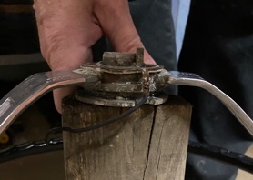
To put the spring back on, set the power wire at the 12 O’clock position and you can use a 1 1/16" or 1 1/8” open end wrench and a rubber mallet to drive it down in place...
-
-
-
-
When hammering the retainer back down support the center of the wheel hub on a 4” x 4” piece of wood maybe 2 feet long so the rim is not touching the ground. Be careful not to let the rim make contact with anything, you could wrap the rim with foam pipe insulation or rags for extra protection and I HIGHLY recommend getting someone to help you hold the wheel while you drive the spring back in place.
-
-
-
Doug Lepak
-
The Steering Wheel Guy
-
8449-14 ave
-
Edmonton, AB
-
Canada
-
T6K1X3
-
780-450-1397
-
GST# 843045477
-
FB page: www.stwheelz.com
Horn Circuit
1968 horn circuit
-
Take apart the middle horn button on the steering wheel and removed the three screws retaining the horn ring to steering wheel hub.
-
-
You will see a little copper wire retainer/holder/tail looking thing looking right at me from the horn contact assembly. That is where a horn wire is supposed to wire to and run through the horn switch and connect to a tab on the horn assembly. No wire is there currently. That copper wire holder (whatever) appears to be a part of a copper ring on the backside of the steering wheel/horn contact assembly.
-
-
There appears to be a roller contact, which connects to the black ground wire, which runs to the horn relay in the steering column. The roller contacts the copper ring on the backside of the steering wheel assembly. The wire does run up the middle and connect to the male tab. When you press on the horn ring the circuit goes to ground and the horn honks.
-
-
This might be as simple as adding the wire that goes from the wire holder, through the horn switch and to the male tab on the horn assembly. I am reading the '68 Plymouth Service Manual, section 8-68. However, it isn't that helpful. I also read through the section on manual transmission steering wheel assembly/disassembly; that didn't help much either.
-
Michael Mosley - ’68 Cuda
-
-
Adjust the roller so that it contacts the copper ring. They are spring-loaded. There should be a wire from the ring to the horn switch. The horn switch makes the ground for the relay.
-
Jim Conner - ’68 Cuda
-
-
There should be conductive grease on the roller and spring.
-
Ron Evans - ‘67 Coupe
Turn Signal Cam (Directional Signal Switch)
Removal
-
Remove steering wheel.
-
Remove screw attaching turn signal lever to switch and remove lever.
-
Disconnect turn signal wiring at steering column jacket tube below instrument panel.
-
-
NOTE: Attach a piece of string to wiring before removing switch from steering column. When switch is removed, leave string in steering column jacket tube as an aid in replacing wires.
-
-
Remove screws attaching turn signal switch to steering column.
-
Remove switch from top of column.
Turn Signal Cam Restoration
-
Found this over on the Slant Six Forum - the thread is by a guy that has a ‘67 Barracuda:
-
"The repair cams are indeed available from many sources, but if you want to do the replacement job once (and not over and over and over), you get the one made by David Koldos (115 Hill Ave, Elgin, IL 60120-4412, (847) 888-2652 ) instead of one of the parts store items. Last e-mail I have for him is dkoldos@ameritech.net , which may or may not be current. He got fed up with the cruddy quality and short life of all the repair cams on the market, and, being a master moldmaker by trade, crafted his own really nice ones."
-
Steve Toth
-
-
He says that it is only for '62-'66. Here is the only website I could find on it:
-
-
This appears to be the same thing on Ebay, but it only says '63-'66:
-
Nathan Nuttall - ‘67 Fastback
Aftermarket Turn Signal Cam
-
For 1962-'63 and 1964-'69 A, B, & C-bodies (without tilt steering). These come with correct configuration, wires, & terminals—No "adaptors", hacks, or modifications needed. Made in OE quality to original Chrysler blueprints by an original Chrysler supplier. This switch, with minor and easy modifications, also fits Studebaker Avanti. $101.90/ea plus $9.90 postage to send up to three at a time in the lower 48 states. Just send me an email to order your switches; specify vehicle years and models.
-
I highly recommend the turn signal cam unit from Daniel Stern. They are manufactured from Chrysler blueprintw and work flawlessly. www.DanielSternLighting.com
-
Angel Garrido - ’69 FB
-
-
PG Classics, Classic Industries and Year One have some for ‘63-66 and ‘70-74. Maybe Tony's Parts back east has a used OEM part.
-
Steve Toth
-
Turn Signal Cam (Directional Signal Switch) Troubleshooting
-
1) With the turn signal lever centered, do the emergency flashers work properly?
-
2) With the turn signal lever centered, do brake lights work properly?
-
3) If emergency flashers and brakes work properly with signal lever centered, the column connector is probably wired incorrectly.
-
4) If wire colors on replacement cam switch are the same as OE, pin 6 should be dark green, pin 7 should be white, and pin 8 should be brown. Looking at the open end of the column connector, with the "key" on your right, pin 6 should be upper left. Pin 8 should be directly across from the key, which is next to pin 3 (tan wires).
-
-
The hazard/flasher switch can probably be taken apart and restored.
-
Sometimes the new electronic type flashers are not compatible with old cars.
-
-
Before you open up your hazard/flasher switch, you should make a continuity measurement. In one position, there should be NO conductivity between any of the terminals. In the other position, there should be conductivity between ALL the terminals. If the switch checks out, it is very unlikely there is anything wrong with it.
-