


Basically, the voltage regulator completes the charging circuit and allows the alternator to charge the system. When a certain preset voltage is obtained, the regulator "opens" (or turns off) the circuit until the electrical system's voltage drops below a certain point, then it turns on again. The old Voltage Regulators are repairable and rebuildable. The 1969 Dodge Shop manual (available from Year One) details how to do this. If you think your regulator is failing, open it up and clean the "points" with some emory paper or light sandpaper. Sometimes these points get corroded and this stops them from working.
NOTE: The FLD is usually green, and the IGN wire is Dark blue on stock Chrysler wiring harnesses.
Wiring
Wiring Problems
-
Wire insulation can get brittle over time, particularly under the hood. Many wiring problems are caused by what other owners have added in the past. Another common connector problem is broken retaining clips on the bulkhead plugs.
-
Jim Conner - ’68 Cuda
Grounding
-
Grounding is what completes an electrical circuit via the body. Poor grounding creates all kinds of electrical issues, from dim lights to erratic accessory operation. Virtually every electrical component is grounded to the body directly or via a ground lead to the body.
Wiring Testing
-
Battery arcing at positive means there is a problems else where. Check starter for cable touching heat shield metal.
-
-
Check Alternator to see if there is a plastic insulating washer between power cable and alternator itself so to insulate before grounding out on alternator. If missing it could cause whole engine to be positive.
-
Fuseable link wire is a fail safe wire. If there is a short, the wire will burn in half saving all wiring on dash, ignition wiring.
-
-
If you have smoke or link is hot, fix problem before you do anything else.
-
Don't ever bypass link.
-
Testing if you have electric power using test light.
-
Ground cable already on battery. Hook up positive power cable to battery.
-
Attach light to ground cable on battery. Touch light to positive, it should light Turn key on all the way. Touch light to ballast resistor it should lighten If turn key off light goes out on ballast
-
Turn on key, Touch light to coil it should light up If no spark when first starting car, check fuses first. Then check relay.
Wiring Upgrades
-
Voltage drop across the bulkhead connector is significant. This impact headlight brightness the most, but can impact other things such as ignition output. I have done a few upgrades to overcome the bulkhead connector resistance. First, I had an electrical fire in the connector which scared me into action. After I replaced the wiring I ran a power lead from the alternator to the amp meter under the dash directly to shunt much of the current around the bulkhead spade connectors.
-
-
Next, when I went to halogen headlights, I ran power to the headlights through Bosch relays with the original circuit being the switch circuit and power from the battery post at the starter relay.
-
-
I then set up a relay system for the ignition but haven't fully sorted this out as there needs to be both a start and a run circuit and it must be through the resister for run to keep voltage to about 8V at the coil.
-
-
Also, to reduce corrosion, pack the bulkhead connector with lithium grease to keep moisture out.
-
-
Power for accessories can be taken from the fuse box using some of the extra lugs or an extender lug (splits to two lugs, but I cannot remember where I got them).
-
-
The only problem with relays is figuring out the wiring with few if any changes to the original wiring in case you want to go back to stock. That takes some thought.
-
Bob Freerks
-
I have wired quite a few systems using the relays. Each connection in a wire results in a voltage drop. If you have any questions on wiring the relays let me know.
-
Darrell Stephens
-
-
I have also bypassed the bulkhead connector with an alternator feed directly to the Ammeter. I also replaced all the connectors in the bulkhead connector and plug - standard connectors available at NAPA - and packed the connector with dielectric grease also available at NAPA. No more bulkhead connector issues.
Cuda Wiring Manual
-
There was no reference to ‘Cudas in '67 Service manual. It was just the Valiant. But there was a supplement for the ‘67 ‘Cuda for the techs. The ‘67 supplement does not have accessory wiring info like the ‘68 and ‘69 do.
-
Daty Rogers - ’67 Conv.
-
-
The accessories would be in the main manual because those would be the same as Valiant. You can use a Valiant underhood wiring harness in place of the Barracuda one. The rest has very little difference.
-
Jim Conner - ’68 Cuda
-
-
The ‘69 switch has an unused terminal.
-
Gerald Drury
-
-
Differences from ’67 and ‘68 same with the exception of the clearance lights, taillights and the hood trim pieces. More differences for ‘69.
-
Mike Jarvie - ’68 Fastback
-
Wiring Diagram
-
The red wire with white trace feeds the dome lamp, cigar lighter, emergency flashers and stop/tail lights fuse blade and dash lights.
-
Jim Conner - ’68 Cuda
-
-
The blue wire with the yellow end is the fusible link that protects the entire system.
-
-
The stop/tail lights feed into the headlamp switch (L8-18Pink). The headlamp switch then feeds the instrument panel (E1-18Tan).
-
-
View this wiring diagram:
Wiring Harness
-
Most vehicles wiring systems are modular in design with the significant portions being:•Engine harness •Forward Light Harness •Dash Harness •Rear Light Harness
-
Many accessories are optional – these optional circuits will have their own harnesses if the vehicle was so equipped (i.e. Air conditioning, Floor Consoles, Power windows....). These harnesses must be obtained in addition to the other harnesses.
-
Aftermarket Wiring Harness
-
http://www.americanautowire.com/shop/1967-1975-mopar-a-body- classic-update-kit/
-
Wiring harnesses should be neatly bundled, wrapped, and protected with some form of conduit like PowerBraid or ClassicBraid from Painless Performance.
-
Jim Smart
Rear Wiring Harness
-
The red wire with white trace feeds the dome lamp, cigar lighter, emergency flashers and stop/tail lights fuse blade and dash lights.
-
Jim Conner - ’68 Cuda
Rear Wiring Harness Disassembly
-
Label the old wiring harness before removing it.
-
Jeff Ramin - ’67 Coupe
Rear Wiring Harness Restoration
-
Clean up the rear wiring harness. Wipe down all the wiring w/ soap & water, soldering some wires, cleaning up tail light sockets so they shine again. Clean all the contacts, test bulbs.
Rear Wiring Harness Installation
-
Compare the old wiring harness to the new one making sure it is identical. If it is, label the wires on the new harness accordingly. Install the rear wiring harness in the car.
-
Jeff Ramin - ’67 Coupe
Factory Wiring Splice under Dash from Alternator
Wiring on a ‘68 fastback. (From the junction)
-
If you unraveled the electrical tape from the factory splice there should be:
-
-
1. Black feed wire (from alternator) 12 gauge runs to bulkhead P. This wire is connected directly to the
-
output "Battery" terminal on the alternator.
-
2. Black wire with trace (goes to headlamp switch) 16 gauge
-
3. Red wire with trace (goes to fuse-block) 14 gauge feeds unswitched power to the fuse box. Cigar
-
lighter, dome lamp, stop and tail lamps, and emergency flasher.
-
4. Violet wire (goes to horn relay) 16 gauge
-
5. Red wire (goes to ignition switch) 12 gauge
-
6. Black wire (goes to ammeter) 12 gauge This one goes to a junction
-
-
7. Red wire (for the "Circuit Breaker for the Power Top")
-
8. Grey wire (for the clock)
-
-
I looked at several ‘68 schematics and they all agree with your list of only 6 wires (‘67s only have 5 because the horn relay is located in the engine compartment). Maybe Chrysler made a late design change and didn't need the 7th wire. The crimp is probably factory, because there is a factory splice shown on the schematic, and if someone added an after market electrical part, there are a lot easier ways to get power than to cut out a crimp splice and then re-crimp it.
-
Ron Evans - ‘67 coupes
Engine Wiring Harness
Engine wiring harness for ‘68 Barracuda
-
Engine Wiring Harnesses come in Forward-to-Front (Headlight and engine harnesses) and a rear body harness.
-
-
With a harness you can make new splices and new connections, but it might be easier to simply replace it and start new.
-
Ray Kuter
-
-
If your voltage to the voltage regulator via the ignition wire is lower than what the alternator is putting out, consider replacing the wiring harness.
-
-
If you are thinking about replacing the engine compartment wiring harness, stay with the original factory wiring coloring scheme.
-
-
If replacing your wiring also do the bulk-head connectors.
Replacement Harnesses
-
The following places sell the harness:
-
-
Evans www.EvansWiring.com
-
ClassicIndustrieswww.ClassicIndustries.com
-
YearOne(M&H) www.YearOne.com
-
Herbs Parts www.HerbsParts.com
-
-
Evans’ harness is perfect and just like the original.
-
Ray Kuter
-
-
YearOne sells the M&H harnesses. Best available stock replacement. Made specifically for each car, the YearOne harness is simply "plug and play."
-
Gerald Drury
-
-
The connectors come pregreased, so they are literally ready to install. Notice the open slots. Often, depending on the application, this will be the case, which will allow you to add additional circuits that might be specific to your car.
Wiring Harness Terminal Connectors
-
A good vendor for the wire terminal ends is Packard 56 style connectors. They are used on the bulkhead connector Buy them from Waytek or NAPA. They come in male and female ends.
-
Michael Mosley - ’68 Cuda
-
-
Splice plugs are used on parking lights, tail lights, etc.
-
The other style plugs onto a spade terminal, such as on the horns, relays, etc.
-
DelCity usually has good prices and selection: http://www.delcity.net/
-
Ron Evans - ’67 Coupe
Engine Wiring Harness Installation
-
First just lay it in place.
Bulkhead Connector
-
Check their bulkhead connectors, particularly the middle plug with the main hot wire and the alt. charging circuit. Over time the terminal connectors (spades) become loose in the middle connector. The hot wire is the Big Red One, that goes through the bulkhead to a splice and feeds everything that is constantly hot. That's the wire that causes trouble at times. If the connection is not secure in the plug and bulkhead connector it can cause a bad connection, high current and heat. It's the wire with the fusible link. When doing so, it becomes necessary to disconnect battery before pulling these connectors. Otherwise you can fry everything!
-
Jim Conner - ’68 Cuda
-
-
The bulkhead connectors are a notorious source of bad connections. If you have never done this before, pull them apart and carefully clean all the brass bits, smear with dielectric grease and reassemble.
-
Also, there is a fusible link (sacrificial length of wire) on one of these. Look for a fat wire that looks toasty. If that is the case, it can be replaced.
-
Max Heim - ‘67 Fastback, 67 Conv.
Rebuilding the Bulkhead Connector
-
If your bulkhead is smoked, why would you assume that any part of the rest your harness isn't compromised. Replace/inspect every inch of it. Replace all the blade connectors in both the bulkhead connector and plugs ( they are available at NAPA - GM connectors). When you finish the bulkhead connector and plugs, pack them with dielectric grease(also available at NAPA) before plugging them together. End of electrical issues and nice constantly bright headlights.
-
Steve Toth
-
-
If your bulkhead connector isn't in bad shape, get a good contact cleaner (not WD30) and clean the bulkhead connector terminals really well. Some very fine sandpaper can be used if the terminals are corroded. As said, coat the terminal ends with the dielectric grease. I even coat the plastic lightly to provide a somewhat waterproof seal. You can get the dielectric grease in the small tear open packs at the counter of most big box auto parts stores. But get a larger tube for other electrical purposes. Coat the battery terminals, lightly coat the spark plug and distributor cap boots, sending unit and sensor terminals and boots, etc.
-
Jim Conner - ’68 Cuda
-
-
The real fix is to remove every female connector and close the loops (you'll understand what I mean by loops when you look at the connectors). My first '67 Barracuda had multiple issues at the bulkhead, so I removed the dash harness and fixed every connector.
-
Jim Lusk
-
-
Since you'll have everything apart, it makes for a good time to clean/check all your terminals on the harnesses on both sides of the firewall for issues and replace as needed. As well as bypass the troublesome ammeter! All of which I did when I put Bills new bulkhead connector in and new engine harness.
-
-
Cleaning and burnishing or replacement of the other terminals. I believe these have been identified as Pacaked 56 terminals that you can get at NAPA. But the key to doing these right is the crimping tool; it has to be the right type or you are wasting your time over the long term. You can alternately use any crimp and then solder, but you have to support the wires properly outside of the connectors; soldered stranded wires will very often break at the end of the soldered section after a while if unsupported and subjected to automotive vibrations.
-
-
With a new or cleaned terminal, I would recommend some getting some silver loaded dielectric grease for the the spade part of the contact; use just a little right on the metal, and rub it into the brass; silver will tend to coat directly onto the brass surface with a little pressure. Don't smear it all over the place, and remove any excess gobs of it. Then use regular dielectric grease on the crimps and other area of the terminals. The silver loaded dielectric grease makes a significant improvement in contact conductivity. The silver loaded dielectric grease can be found on eBay and from other sources.
-
http://www.forabodiesonly.com/mopar/showpost.php?p=1970195180&postcount=39
-
http://www.forabodiesonly.com/mopar/showthread.php? t=222093&highlight=bulkhead
Aftermarket Bulkhead Connector
-
Call up Bill Evans at Evans Wiring and order a new one. $70 may seem a little pricey but to me it was worth it. www.evanswiring.com
-
-
Mitchell Motor Parts should have them but they’re expensive there. Classic Industries, Laysons, Herbs, Mega Parts USA might have pieces. Buy M&H from YearOne. they are the best out there.
"Butt-Splice" Connector
-
A common electrical item that fails are crimp-style electrical connectors, also called "butt-connectors". These connectors, if not crimped tightly, will come loose or the wires may work themselves loose due to car vibrations. When this happens, the electrical connection is lost and the circuit becomes dead. And there is a chance the exposed wire may lead to electric arcing that may cause a fire. Butt- connectors are not weatherproof and have no real protection from corrosion. This again may cause the connector to lose conductivity. SpliSeal has developed a tool kit to correct these two butt-connector issues.
-
-
The kit contains a 110v hot sealant gun, sealant, and an aluminum mold, which are used together to seal the butt-splice with sealant that strengthens and weatherproofs the connection. First, wires are crimped together, then the connector is placed in the provided aluminum mold. The top of the mold is then installed and held in place with a small C- clamp. The sealant gun injects sealant into the mold. Once the sealant cools, about 60 seconds, the mold is disassembled. You then remove the sealed connection from the mold, and the excess sealant is simply broken off. You now have a tight, weatherproof connection.
-
SpliSeal www.Spliseal.com
Power Splice
-
The infamous power splice is located under the dash under the taped bundle between the ammeter leads and the ignition switch. The large black wire is coming from the ammeter, and the large red one is going to the ignition switch.
-
Ron Evans - ’67 Conv.
-
-
There is a site for eliminating the power splice, it shows it on a Dodge pickup to convert to volt meter. http://www.madelectical.com
Dash Wiring Harness
Main Dash Buss - Underdash Wiring
-
The red wire with white trace feeds the dome lamp, cigar lighter, emergency flashers and stop/tail lights fuse blade and dash lights.
-
-
The blue wire with the yellow end is the fusible link that protects the entire system.
-
The stop / tail lights feed into the headlamp switch (L8-18Pink). The headlamp switch then feeds the instrument panel (E1-18Tan).
-
-
View this wiring diagram: http://www.jefframin.org/library/BarracudaDashWiring.jpg
-
-
Factory splice under dash from alternator Wiring on a ‘68 fastback
-
If you unraveled the electrical tape from the factory splice there should be:
-
Black feed wire (from alternator)
-
Black wire with trace (goes to headlamp switch)
-
Red wire with trace (goes to fuse-block)
-
Violet wire (goes to horn relay)
-
Red wire (goes to ignition switch)
-
Black wire (goes to ammeter)
-
Jon
-
Additional Harness
-
There are different harnesses and add-on harnesses depending on the options on your car. My Dart wasn't ordered with a console tach, but it has one now, so I had to add the trigger wire to my original harness. My friend has a console tach in his car, and the part numbers for both harnesses are the same...the tach wire is added on the assembly line.
-
Darwin
-
The A01 light group was a set of additional small harnesses which simply plugged into the standard harness. It tended to include a glovebox light, a ignition switch light, a trunk light and maybe a console light (not sure on A-Body if that came with console or only with light group). You can add this option to your car.
-
-
If you look at the wiring for these items in the factory service manual, you can see where they hook into open connections in the main harness. The glove box light is simple and connects to orange wires with a bullet connector into a 3 way female near the ash tray. The trunk light involves a wire which runs from the trunk to the left kick panel and has male and female connectors which put it in the middle of another circuit. The ignition light includes the light mount itself with a blue plastic bulb cover in the bracket and a small silver cylinder with a capacitor for the timer which turns off the light. I forget exactly where this wires in, but it goes into a circuit which includes the driver side door switch similar to the dome light circuit.
-
-
The factory service manual will show you all the details and wire color codes and give you are cartoon picture of the connectors. Once you study it a little against some circuits you do have, you’ll get used to their style. Lots of info in those wiring diagrams including colors, gauge of wire and connector types. Only thing lacking is actual wire lengths and locations of connectors.
-
Todd Rimmer - ‘6
Aftermarket Dash Wiring Harness
-
The generic harnesses that are sold by Classic, and by many other places, are made by M&H. Laysons, Herbs, Mega Parts USA have pieces.
-
Buy M&H from YearOne. They are the best out there. Made specifically for each car, the YearOne harness is simply "plug and play." The connectors come pregreased, so they are literally ready to install. Notice the open slots. Often, depending on the application, this will be the case, which will allow you to add additional circuits that might be specific to your car.
-
-
Darren at M&H is very patient and very good at answering questions, so give them a call. They will reproduce the sub-harness you are looking for if you bring them your original harness to work from.
-
They are located in Santa Fe Springs.
-
Ron Evans - ’67 Conv
-
-
Evans Electric make wiring harnesses for mopars (and mopars only). They are very accurate. They are a supplier to these larger reproductions companies like Classic Industries. Evans Electric is a mom and pop joint. They get high marks. http://www.evanswiring.com
-
Enrique Aguirre
-
-
Here's one option to start with: A painless wiring kit with NO bulkhead connector.
-
Steve
-
-
The painless wiring harnesses for Chryslers are actually GM color coded.
Firewall Grommets
-
Local hardware stores usually have a better grommet selection than parts stores. I rewired my car, going through the firewall, bypassing the bulkhead connector and using rubber grommets. I got all of mine from Ace Hardware.
-
Jim Conner - ’68 Cuda
-
-
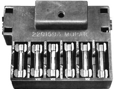
Fuse Box
-
The fuse box is located on the drivers side of the dash just to left of the steering column. It is held to the bottom of the dash frame with one self-tapping screw. A thin plastic velum covers the wires to keep dust off of them. This is usually brittle or gone after 50 years.
-
-

-
Fuse Box Problems
-
Fuse box terminals invite corrosion and eventually will fail. If your fuse box terminals are corroded,
-
they can be a pain in the butt to get clean. Wire insulation can get brittle over time, particularly under the hood. Many wiring problems are caused by what other owners have added in the past. Another common connector problem is broken retaining clips on the bulkhead plugs.
-
Jim Conner - ’68 Cuda
-
-
Sometimes the blades on the back of the fuse box become loose. Fuse box terminals invite corrosion and eventually will fail. If your fuse box terminals are corroded, they can be a pain in the butt to get clean.
Fuse Box Restoration
-
Think about taking it apart, cleaning it up, soldering the loose connection, and then putting it all back in. Be sure to label all of the wires before you start taking it apart.
-
Good dielectric grease is an absolute must when reassembling wire connectors.
-
There was a thin clear plastic velum placed over the wires in the box from the factory. This is usually missing after years in the dash. Just make a cheap replacement from thin plastic.
Aftermarket Fuse Box
-
I purchased the RTA 88 fuse panel from Hay Wire. www.haywireinc.com. It is expensive, but I felt it was worth it. This fuse panel comes with seven fuses, 2 flashers, horn relay and radiator fan relay. So I can make some room under the dash by removing the horn relay and flashers. I extended all of the wires so that I can work on the fuse panel while it is on the driver's side floor board. The instrument lights are actually brighter and the tail-lights work again.
Reproductions on ebay
-
http://www.ebay.com/itm/1963-64-65-66-67-68-69-70s-NOS-MoPar- FUSE-BLOCK-Cuda-GTX-Runner-300-Fury-Dart-GT-/ 400460648208#vi-content).
Fuses
-
Fuses come in different sizes. Which ones you need depend on your circuit. Check the Chrysler Parts Fuse Guide to determine what you need.
-
-
-
-
Here’s what is required for my 1969 Barracuda:
-
-
Back-up Light, Radio SFE20 IP or AGC 7-1/2
-
Cig lighter, Glove Box light, Map Light Parking Light SFE20 IP
-
Directional Sig.Emergency Flash SFE20 IF
-
Dome light SFE20 IP
-
Headlight Dimmer SFE4 IF
-
Heater SFE20 IP
-
Instrument Lights AGC2 IP
-
License Plate light, Parking Light, Tail Light SFE20 IP
-
Radio AGC 7-1/2 IP
-
Stop Light, Dome Light SFE20 IP
-
Tachometer, Accessory SFE20 IP
-
Trunk Light, Dome Light SFE20 IP
-
-
IF= In Fuse Holder
-
IP= In Panel or Main Fuse Block
Miscellaneous
Alternator
-
The parts are not interchangeable between 1969 and earlier and 1970 and later. The alternator mounting brackets are different and the pulleys are different.
-
Darrell Stephens
-
-
On the ’69 318, there are two spacers on the alternator - one between the bracket and water pump, one between the alternator and head.
-
Jim Conner - ’68 Cuda
-
-
On the ’68 Barracuda, the alternator mounting bracket uses a small spacer at one of the bracket / water pump bolts.
-
Alternator Types
-
In '67-'69 we had Single Field Alternators. In 1970, Mopar had Dual Field Alternators. Functionally the single field and dual field alternators are pretty much the same with one caveat. There are two ends to the field coil in both. So, the “old style” regulates the voltage on the positive side and the “new style” regulates the voltage on the ground side of the field.
-
-
The alternators both have a single rotor winding and single 3-phase stator winding. The difference is whether one or both rotor winding leads are brought outside. The model with the single field terminal has the other rotor lead internally grounded, and is intended for use with a mechanical voltage regulator. The model with both leads brought out is intended for use with an electronic regulator. In the first case, the regulator applies +12 to energize the rotor. In the second case, one terminal is connected to +12 via the ignition switch and the voltage regulator modulates the ground connection on the other terminal.
-
If you are using an electronic regulator, you need an alternator with two field terminals. The 2-terminal alternator can be used with a mechanical regulator if one of the field terminals is externally grounded.
-
Ken Mayer
-
-
The old one has one control wire from the regulator and the field grounds thru the frame.
-
-
The newer type uses two wires to isolate the field circuit to the regulator only.
-
The newer type alternator is “isolated field”.
-
-
There are electronic one wire regulators now and that may be all you need for the older system to produce stable voltage for the electronic ignition. I have run a one wire alternator on my Cuda ('68) with no issues with a Mopar electronic ignition. I don't think the MSD is that sensitive to voltage changes to worry excessively about the alternator or voltage regulator.
-
-
-
“single field” Alternator
-
In the “single field” or single spade terminal alternator has the positive end of the field external with a spade connector. The ground end of the field is grounded internal to the alternator case. You only have two connections, the spade connector that goes to the “FLD” connector on the “GRC-724” style regulator and the large gauge 12V wire that goes to the amp meter.
-
-
“dual field” Alternator
-
On the “dual field” or two spade terminal alternator both ends of the field have spade connectors. Now here is the essential difference. One of the spade connectors goes to an ignition hot 12V source, and the ground end of the field goes to the corner pin on the regulator.
-
-
The square back alternators are far superior to the older round alternators both in terms of reliability and serviceability (the diodes just snap in, not soldered in). And the output is much higher. But this would require careful selection of wiring from the alternator to the battery to handle the additional current load and definitely would require a rerouting of at least some of the current away from the bulkhead connector and amp meter in the dash. A 4 gauge wire from the alternator to the battery with a 60 A fusible link should do it.
-
Bob
-
Reasons for Using a Particular Alternator
-
You want more amperage than the stock (46 I think) I have used a 60 amp dual and grounded the second field to get enough power for the hotter spark required to run a "big" ignition.
-
Alan Morasch
-
-
I like our single. I have MSD in our ’67 and ’68 and no issues. Both running higher output than stock. On is 95 and the other is 135.
-
Bill Lewis
-
-
I think there is no need to change the charging system if it is supporting all the light, etc. and keeping the battery charged.
-
-
I put the isolated type on my ’69 FB and the obvious difference was better charging at idle.
-
-
The original system worked but the headlights would dim at idle and original mopar air conditioning made that situation worse! You’ll need the matching regulator and IIRC just add another field wire to the alternator. And the two field wires are interchangeable, no positive or negative.
-
-
1) If you have a field terminal on the alternator, you need the original type regulator
-
-
2) 2 things things affect whether you need a ballast resistor, the coil and the points. If you have an MSD box with an MSD coil (or other modern coil), the coil will be OK with out a ballast resistor. But, if you still have a points type distributor, you should use a ballast resistor to give the points longer life. Here's a good article: https://www.hotrod.com/articles/mopp-1110-ballast-resistor-guide-ballast-blast-off/
-
Ron Evans
Alternator Date Codes
-
There is Identification on the front and back part of the alternator that looks like a pie chart. The middle most number is the year the alternator was cast (i.e. 69). The pie chart around the number is the week or month it was. There are dots in each pie slice. If there were 3 dots punched in the pie slice, to read you go on to the next pie slice. One dot represents the first week of that month (i.e. - first week of October).
-
So an alternator has to be built before the car was built. And not the same day either. A sweet rule is the alternator being built a month to 4 months before the car was built.
-
-
The front and back pie charts should match. There is however a final assembly date. On the bottom is a date of final assembly (i.e. 11-69). That is the 11th week of 1969. So casting dates should precede final building date. A lot of Mopar parts use the same type of date coding like: starters, thermostat housing,
-
Graveyard Cars
-
Alternator Grounding
-
After replacing the single wire, mechanical regulator with the newer alternator and 2 wire, ( blue to 1field and green to the 2nd field ), make sure you have a really good ground on the new style regulator! Otherwise it's really an easy upgrade. Now both the amp-meter and volt meter read what the system is doing.
-
-
When replacing a one field car alternator speaking, green wire, with a two field alternator, you have to place a ground wire from one of the alternators fields post to a ground. It does not make a difference which post you ground.
-
Jim Lusk
-
-
...unless you want to change to the isolated field regulator. Then you just run that extra field wire to the new regulator.
-
Darwin
-
Alternator Bracket Restoration
-
Degrease / derust the alternator bolts and spacers. Take the wire wheel to the bracket. Put a coat of POR15 on the alternator brackets later.
-
Jeff Ramin - ’67 Coupe
-
Alternator Installation
-
The easiest way to mount the alternator is by loosening up the bracket, so you don't have to squeeze the sleeves into place. Make sure one ear goes on the front side of the alternator bracket. So, the square back alternator will fit just fine. Note: The ears on the alternator DO NOT go between the cylinder head and bracket. Don’t forget the spacer. Avoid stripping out the bolt hole in the alternator which gives tension to the fan belt.
-
Jeff Ramin - ’67 Coupe
-
-
A simple way to connect an ammeter on a voltage reg/horn relay system (GM/Chrysler) splice ammeter positive and negative leads into wire from battery positive to voltage reg.
-
Aftermarker Alternator
-
If you have problems blowing alternators or voltage regulators, put in a new style alternator with internal voltage regulator (one wire powermaster chrome alternator). Some use a 136 amp alternator for a 1998 Dodge Dakota.
-
-
Powermaster come in one-wire alternator, or a stock type. If you got a one-wire, the voltage regulator is no longer used, because there is a voltage regulator built into the alternator.
Alternator Restorers
-
Dixie Restorations do a complete disassembly and inspection followed by a thorough proprietary case cleaning. Diodes/rectifiers, brushes, and front case bearing are replaced. Your rotor, stator, front bearing retainer, capacitor, original insulator, and brush holder are replaced or reconditioned to "like new" appearance and function. All case hardware is re-plated or replaced as needed. OEM rear case bearing is re-plated or replaced. The alternator pulley is carefully reconditioned or replaced. The appropriate factory markings are restored. Base cost for this package is $250.00
-
*Developed specifically for Dixie Restorations to produce an OEM finish w/o loss of detail. **Replacement @ additional cost.
-
Dixie Restorations
111 Aull Street,
Pomaria, South Carolina 29126
(803) 924-6247
Alternator Bushings
-
The single pulley alternator has a bushing between the engine block and the alternator. It is about 1-1/8" long but the alternator pulley needs to be about 1/4" further forward to align with the water pump pulley. You’ll need a bushing about 1-3/8" long.
-
Ed
-
-
You can just use washers to space it out the extra you need.
-
Phil Saran
Alternator Mounting Spacers
-
The spacers come in different lengths. Apparently, 1970-later spacers are different than pre-1970. For small blocks, 1970-74 spacers are different than ?-1969. They come with a conical washer and bolt.
-
Ed Lexus
-
-
Ebay sells the spacers. A set of spacers for the ‘68 Barracuda SB sell for $13 shipped.
Chromed Alternators
-
A chromed alternator is much, much easier to keep shiny than a polished one - from someone I talked to at a car show. Coating the polished aluminum parts with a clear coat makes them a lot easier to keep clean.
-
Ron Evans
Ammeter Bypass
-
Some people take the ammeter out of the alternator circuit to eliminate that current going through the bulkhead connector. My new alternator connects through the power dist. box anyway. According to the wiring diagram something else connects to the large red wire on the ammeter terminal.
-
Jim Conner - ’68 Cuda
-
-
One side of the ammeter is connected straight to bulkhead terminal J. This is a 12 gauge Red wire. On the engine compartment side this goes to the fuse link and connects to the battery terminal on the starter relay.
-
-
Other side of the ammeter is a 12 gauge Black wire. This one goes to a junction. If you bypass the Ammeter you essentially would run the 12 gauge Black that used to go to the junction and connect it to the 12 gauge red wire that is fed by the fuse link. If your alternator feeds the fuse link (or those circuits are otherwise fed) via the power distribution box, then you do not need to connect anything to terminal P.
-
Michael Mosley - ’68 Coupe
-
-
Ammeter Check out this link for an explanation of how the ammeter circuit works and what are the common Chrysler design issues:
-
http://www.madelectrical.com/electricaltech/amp-gauges.shtml
-
-
To retain an ammeter, you need to deal with the bulkhead connector issues described in the article in the future. What I did was retain the circuit in part 1 of the article with one significant difference:
-
1. Upgrade the ammeter wires to 10 gauge and bypass the bulkhead connector. Ran #10 wire to and from the ammeter through a rubber grommet protected hole in the firewall.
-
2. #10 wire thru firewall from the fuseable link to the positive post of ammeter
-
3. #10 wire from the negative post of the ammeter to the welded splice and then through the firewall to the alternator.
-
4. Don't forget to connect to the welded splice! It supplies power to all the car's circuits.
-
5. Don't forget to check the posts on the ammeter and mark which one is positive and which one is negative when you unhook everything - if you hook the ammeter up backward the needle will indicate negative when it should be indicating positive.
-
6. After you crimp ring terminals or 1/4" blade connectors on the wires, take the time to also solder the wires into the terminals - insert the wire a little past the terminal barrel edge so it sticks out a little towards the ring or blade, then solder that end of the wire to the terminal or
-
blade. The first part of the crimp on the wire insulation takes up the strain, the second part of the crimp on the bare wire makes an electrical connection and the soldering of the wire to the terminal ensures the connection will stay good.
-
Steve Toth
Electric Ammeter Bypass
-
Is the MAD electric ammeter bypass really worth doing on our cars? The issue I have with the MadElectrical diagrams is they never mention the voltage regulator. In diagram B (link below) with our factory electrical system, would you still come off the ignition with a wire to the voltage regulator when you have the charge wire going directly to the battery/starter relay/distribution block? The voltage probably will not be the same (off of ignition vs at distribution block).
-
http://www.madelectrical.com/electricaltech/amp-gauges2.shtml
-
-
In Diagram B, if they did not bypass the ammeter, would it still provide an accurate amp reading? I would think so, but maybe I'm missing something.
Ballast Resistor
-
The ballast resistor is just a resistance coil no different than a light bulb filament, or stove burner. It will conduct electricity if good, and won’t if bad, in other words if the resistance coil is still whole not broken it will work to step down voltage. If it is open, or rather its coiled wire has broken into two disconnected lengths of wire, it won’t conduct electricity just as a burnt out light bulb filament opens the circuit.
-
-
The way it should work:
-
Mopar ignition design utilizes two current paths; start and run. When ignition key is in start position turning over engine, start circuit bypasses ballast resistor providing coil with 12v for easer starting. Once engine catches, and key is released flipping back to run, power is diverted through ballast resistor to step down voltage to a coil friendly 5 to 8 volts depending on its resistance value.
-
-
When ballast resistor fails, the engine will start and run as long as key is in start position bypassing ballast, and once key moves to run, engine dies. Occasionally ballast resistor will selfheal like a light bulb sometimes dose by self-welding filament back together only to soon fail once again; this almost never happens.
-
-
Two things affect whether you need a ballast resistor, the coil and the points. If you have an MSD box with an MSD coil (or other modern coil), the coil will be OK with out a ballast resistor. But, if you still have a points type distributor, you should use a ballast resistor to give the points longer life. Here's a good article: https://www.hotrod.com/articles/mopp-1110-ballast-resistor-guide-ballast-blast-off/
-
Ron Evans
Battery
-
Most older cars used sealed lead acid battery, (newer models may use lithium ion battery). The lead acid batteries that our cars use, is 12V (12.6V to be precise, 2.1V per cell and has 6 cells. A fully charged battery connected in the circuit is about 13.3V). And car batteries usually have high cold cranking ampere, which means for short burst it can provide very high amount of DC current. Which side the + and - terminals are on is defined by "S" or "F".
-
-
We need the 24S or 27S. In the event you ever have trouble starting the engine, the group 27 will crank the engine over for a longer period of time, so you should definitely get a group 27. In general, try to get the battery with the highest cold cranking amps (CCA) rating, that will fit on the battery tray.
-
Ron Evans - ’67 Conv.
-
-
-
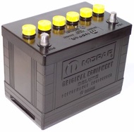
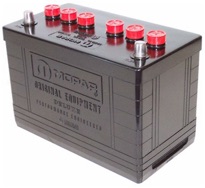
Group 24 Group 27
-
-
Both Group 24 and Group 27 (longer) fits in the battery tray. The group 27 battery is about 12" long, while the group 24 is about 10" long. The Group 27 is 0.12" less tall and 1.8" longer than a Group 24. They are both the same width and height, so you can use a stock battery hold down for both of them.
-
Ron Evans - ’67 Conv.
-
-
Chrysler put Group 27 batteries in big blocks or hi-perf engines and their big station wagons with lots of electrical needs.
-
Ed
Battery Recommendations
-
I buy whichever one has the highest reserve capacity and the same post configuration as the group 24.
-
Nathan Nuttall - ’67 Fastback
-
-
I have been getting 7-8 years life on average on the 84-month rated batteries, so they live up to their rating.
-
Max Helm - ’67 Fastback
Battery Installation
-
When hooking up battery, hook up red (+) first. then black (-). This so if wrench touches there is no ground out and no sparks.
-
Garage Squad
Battery Troubleshooting
-
Battery arcing at positive means there is a problems else where. If the ground post clamp has a crack, from experience this leads to a flat battery (you think it’s tight, but it’s not).
-
Max Heim - ’67 Conv.
Battery Cable
Original Battery Cables
-
Original battery cables are probably the easiest thing to spot as they are right in front, and they differ so much from originals to reproductions.
-
Original battery cable wires have a spine. On the red positive there are two wires on the pattern post leading off, look for the spine on both positive wires.
-
-
Supplies of NOS wiring harnesses are nearly impossible to find, however there are many original harnesses out there still if one is so inclined to look.
Repro Battery Cables
-
Even though some of the reproductions are made here in the states and are of very good quality, they differ visually. To the left you will notice a comparison photo of an original (on the right) vs. a reproduction (on the left). The most noticeable difference is the colors of the lead wires.
-
-

-
-
You will see the original cable uses two different colored wires. Also note the original cable has a bolt with a very thick head-almost twice as thick as the repo. Every original cable has the head shaped as shown. Some later NOS cables had a flat/squarish head that is not correct, even if it came from Chrysler! Another important detail is that early cables used an imprinted ink to identify the part number, whereas later models used paper wrapped wiring harness tags. This is true across the board in wiring sometime in 1969. A worker at Chrysler explained that the paper tags were much easier to read and didn’t require specific wire to be used in a harness. So a 1968 cable came with an ink stamped part numbers vs. a 1969 cable with a paper part number tag. Sometimes the Chrysler part number did not coincide with the part number tag on the cable itself.
-
-
There is much more information on battery cables and many other components in the ICCA restoration reference manuals. www.mmcdetroit.com
-
Battery Tray
Restoring Battery Tray
-
Degrease / derust the battery tray support bracket. After you clean it up, put a coat of POR15 on the battery tray.
-
-
Originally the battery tray was painted the body color.
Battery Hold Down Clamp
-
Many years ago I bought a "z" clamps battery hold down, from YearOne, that are supposed to be for these cars years. It has never fit right on any group 24 battery that i have ever bought for my '67. The batteries are always too small, or the clamp is too big. The clamp is a well made piece and still looks nice after all these years and looks identical to all of the "z" clamps that I see for sale now but it is just too big. I want a battery hold down clamp that fits a group 24 battery without hanging off the edges of the battery. I don't care if it is a Mopar authentic piece or not, just something that looks decent, is black and looks reasonably appropriate for the car.
-
Jeremy - ‘67 Coupe S
-
-
If you bend the angles in the Z to make them more acute, it will have the effect of narrowing the space between the two sides -- that might help, assuming it still fits between the battery caps, and the j-hooks still line up more or less.
-
Max Heim - ’67 Conv.
-
-
This type fits good and works.
-
O'Reilly Auto Parts Super Start® 01328 - Battery Hold Down I found a top piece that was the right size for the battery, and just made the posts to fit. All you need is a metal post that has the "twists" already put into it with the wing nut & you can bend the bottom part (& cut if needed) to fit. Most of the bottom does not show anyway & the price is hard to beat.
-
Barry - ‘Cuda Conv.
Ballast Resistor
Ballast Resistor Troubleshooting
Coil
-
Sometimes you have trouble with spark. The ballast resistor apparently should measure less than 1 ohm cold (0.5 or 0.6) and less than 2 ohms hot. I just checked mine, and it reads 2.4 ohms cold. The point was that too much resistance weakens the spark. Changing the ballast should solve the issue.
-
Max Heim - ’67 Fastback, ’67 Conv.
-
-
Voltage to coil should be 12+ volts at all times. Low voltage to the coil means coil can't produce enough spark at the plug.
-
No spark = no combustion.
Ignition Switch
-
The switch is supposed to have continuity to the accessory terminal when you turn the key to the left.
-
There should be two ACC positions. Only one is hot when the switch is rotated to the left.
-
JIm Lusk
Troubleshooting
-
If no spark when first starting car, check fuses first. Then check relay.
-
I was testing my ignition switch before the rewire and can't find an accessories position. When I turn the key all the way to the left, I don't have continuity between BAT. and ACC. I do have continuity when I turn the key to the run position.
-
Jim Conner - ’68 Cuda
-
-
The ignition terminal would behave that way. Are you sure you have the accessory terminal?
-
Ron Evans - ’67 Conv.
-
-
Yeah - you kinda have to push the key in a little bit to get the switch to go into accessory mode. I had the switch in one hand, the ground lead from the multimeter in one hand, and the positive lead from the meter in the other hand.
-
Jim Conner
-
-
Yes, the switch is supposed to have continuity to the accessory terminal when you turn the key to the left.
Starter
-
Nothing else sounds like the original Chrysler gear reduction starter.
Replacing Starter on a Small Block
-
It’s not hard. 2 bolts. You can do it from underneath. The only tricky part is rotating it so that it fits around/between the torsion bar and the exhaust. It only fits in one orientation, but I can never remember what that is without trial and error. The other factor is that it’s a little heavy to be holding up with one hand while you’re doing that.
-
Max
-
-
No headers a pretty easy task, some headers will make it hard though. Disconnect the battery first either way!
-
-
It’s a half hour job without headers.
-
-
I find it is easier to do if you remove the pitman arm from the bottom of the steering box. Then it just slides right out. Removing the pitman arm is easier than removing the center link connection to the arm, and after you do this, you can move the steering completely out of the way. Pulling the pitman arm is really easy with the puller so it doesn't take much effort. This is more important if you have headers that are taking up a lot of your room.
-
Nathan Nutthall - ’67 FB
-
-
They are talking about cars with headers, where space is much tighter. Easier to pull suspension apart than to remove a header.
-
Max
-
-
I’ve been lucky by just turning the steering wheel (which moves the pitman arm) to a certain position.
Restoring Starter
-
Degrease the starter with Simple Green and a wire brush. Use a screw driver and shop towels after that to clean out all the nooks and crannies. Then derust the armature using a combination of sand paper and the wire wheel. Then put a coat of POR15 on it.
-
-
Test the starter by hooking it up to a battery. The gear should pop to the end of shaft when you apply juice. Put a top coat of grey on the armature.
-
Jeff Ramin - ’67 Coupe
Solenoid
-
The solenoid is mounted on the starter.
Starter to Bell Housing Stud
-
The finish should be zinc.
Starter Replacement (Original)
-
Get a quality rebuilt unit, and unless you NEED the higher-torque version with the longer winding end, the shorter version might be easier to install. You can make that call when you’re removing the old one. If R&R isn’t a problem, the longer higher torque version is a nice upgrade.
-
Clair Davis
Starter Replacement (Alternative)
-
Put in a Dodge Dakota mini starter. The mini starters are just easier to fit with headers, and in general easier because smaller & lighter.
-
Max
-
-
The Dakota starter really spins the engine over quickly, but sounds more new-carish. It angles out a tad more than the old starter. And weighs about half as much.
-
-
The original Mopar starter is much more expensive to work on and is more prone to issues than the Denso starter. I took a few Denso starters off Durangos and Rams, replaced the contacts (cheap to do), cleaned and lubed the rest of the starter and have had no issues at all with them. They are lighter and more powerful than the original. But I would suggest getting the wiring from the battery to the starter when you pick up a used Denso so that you can modernize the connections.
-
Bob Freeks
Starter Restorers
-
Dixie Restorations do a complete disassembly and inspection followed by a thorough proprietary* case cleaning. Brush housing and bendix (five roller HD) are replaced. Stator windings and armature are inspected, continuity tested, and replaced if necessary. Worn shaft bushings re-knurled or replaced as necessary. All internal hardware is inspected, re-plated or replaced as necessary. The stator winding housing is carefully cleaned and then repainted to an OEM appearance. Please note: Most original bendix gear covers found on factory installed CC starters (1968 through 1971) were finished in a thick dark olive drab coating. Much less common prior to late 1970 was an electro-plate galvanized finish. At this time we are unaware of any U.S. company that will provide small parts electro-plate galvanizing. If the original finish on your core's cover has been degraded and cannot be restored, we substitute a black oxide finish on this stamped metal piece. Base cost for this package is $225.00
-
Dixie Restorations
111 Aull Street,
Pomaria, South Carolina 29126
(803) 924-6247
Starter Relay
Starter Relay Wiring
-
The wiring for the starter relay is on the left fender. The original starter relay only has three terminals on it. One big terminal for the battery wire and the large wire going to the starter. The other two terminals use a smaller gauge wire. One wire is wired to the start function of the key, the other small wire goes to the starter. The relay does not have a specific ground terminal on it. The relay is grounded when relay is bolted to the fender.
-
Darrell Stephens
-
-
Basically, one fat one from the battery + terminal, another fat one to the starter, one wire goes hot when u crank the key, and the 4th wire to the Trans neutral safety switch (or on the shifter).
-
The main battery positive cable goes directly to the starter.
-
-
WIRE 1
-
From the battery positive terminal clamp, a wire (like 10 gauge) splits off the battery clamp and goes to the relay.
-
WIRE 2
-
From the relay, another wire similar to Wire 1 goes to the starter solenoid.
-
WIRE 3
-
Smaller gauge wire from ignition switch (trough bulkhead connector). Goes hot when u crank the key.
-
WIRE 4
-
Smaller gauge wire from neutral safety switch. Does not allow starter relay to complete the circuit unless it's in neutral or park. As far as I recall, this terminal goes to ground when the Trans is in Park or N.
-
You can test each of these functions at the fender relay wires (disconnect them first) using a voltmeter.
-
Ed
-
-
That wire is + going from the starter relay to the starter solenoid. The small wire on the bottom left is + from the ignition starter switch to the starter relay coil.
-
-
The small wire on the bottom right is the neutral safety switch. When the transmission is in neutral, it grounds the starter relay coil, allowing current from the ignition starter switch to flow through the coil and close the relay contact, which then connects + to the starter solenoid wire you asked about. I'm not judging whether it's right or wrong, but some people just connect the neutral safety switch wire to chassis ground at the relay mounting screws, so they eliminate any possible problems in getting a good ground from the neutral safety switch circuit.
-
Ron Evans - ‘67 Coupe & Conv.
Starter Relay Wire Mounting
-
The finish could also be Zinc (yellow) dichromate.
Voltage Regulator
-
The Chrysler engineers of the day put good pieces out. Regrettably they are all gone. When the correct pieces were used they were extremely reliable.
-
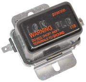
Note: not all voltage regulators with a FLD and a IGN connection are interchangeable!
-
Factory Voltage Regulator
-
The factory voltage regulators had warning information on the outside.
-
1
-
2
-
All ’67 cars had red lettering.
All ’69 cars had yellow lettering. -
Some ’68 cars with a build date of 2 February had red lettering.
Some ’68 cars with a build date of 11 June had yellow lettering. -
Factory Voltage Troubleshooting
If your voltage to the voltage regulator via the ignition wire is lower than what the alternator is putting out consider replacing the wiring harness. -
You can run a 10 gauge wire from the alternator straight across the front of the engine (in plastic conduit) to the starter relay (really to a distribution block, then the relay). Information is available at the Madelectical (MAD) site.
-
The factory wire runs from the alternator to the bulkhead and on to the fuse block or ignition switch.
Solid State Voltage Regulator
-
The polarity of the field is reversed in the newer units! Which is why the V-regs also changed.
-
Gerald Drury
-
-
If using a solid state voltage regulator wire up your headlight relays to control the headlights per the madelectrical website. The blue VR only supplies voltage when necessary, just like the old mechanical, BUT it provides the proper voltage because the electronic box (all of them) require a minimum of 10v to operate. I have never had a blue VR cause a box failure, but I have had several blue VRs fail over the years. It always seemed to be after the car sat for a prolonged period of time. I switched to an aftermarket solid state quite a few years ago.
-
Jim Lusk
-
-
Why not use the solid state units available today that look and connect like the originals in the old style case. They work as well as the blue units mopar use to sell for electronic upgrades. I am using one with a Pertonix III in a factory dizzy and it charges and performs to my expectations. Best part is it looks bone stock. Great for keeping the engine bay looking original. Put the Pertronix in and most people look and think it is an original point set-up.
-
Gerald Drury
-
-
There is a solid state version of the “old style” regulator. Echlin VR-1001 or Standard VR-128. I would get that if you want to use a “single field” alternator and want the under hood of the car to look somewhat stock or do not want to change your wiring. The solid state regulator should give you more consistent voltage than the old points style. If you are having trouble locating an “old style” single field alternator you have the option of using a dual field and just running a connector from the second field to a ground, you can even use the alternator case itself for the ground. May want to run a ground wire from the regulator mount screw to the block and a thick ground strap or wire from the alternator case to the engine also. Make sure you have good grounding.
-
Michael Mosley
-
Blue Regulators
-
The blue regulator was a requirement for installing electronic ignition on pre-70 vehicles with the single field alternator. Pre-70 blue regulators were used for different year models with the appropriate charging system.
-
Gold Regulators
-
The Gold ECU was recommended for Race only!
-
Orange Regulators
-
Use the correct piece for the older alternators (Blue) and for dual field alternators the (Red). Also the correct ballast for each.
-
-
A Gold box and pre-70 blue regulator work perfectly and were purchased in 1984. My decision not to use them in my restoration was purely to make the engine bay look like it did in 1969. When I put the car together I installed the orange ECU which came with the MP crate motor. I installed the MP voltage reg and fried the orange ECU. So I bought the chrome ones and those went bad. Changed to a aftermarket VR and haven't had a stitch of problems. It's always been the same BR since I first put the engine in.
-
Dave
-
-
I also found out that the blue MP voltage reg. gave me serious problems frying ECUs. I replaced 2 of the chrome ECUs because they got fried. I was told that the MP VRs are great for racing, but not for the street. Something about the current going into the ECU. What I did was
-
bought a gold colored single wire VR, a new chrome ECU and it has worked fine for years. I do keep a extra ECU, VR and BR in the trunk though.
-
-
I kept ruining alternators and regulators on the ‘Cuda until we went to a single wire unit with built in regulator! Since then no problems at all, knock on wood!
-
Mike J.
-
-
You don’t have to do anything special to hook it up, it is just plug and play.
-
I have been running an electronic one ever since I bought my '68 FB (part # V101 from Autozone for about $45. It is flatter but it will plug and play. They work great! No more headlight flicker!! No problems.
-
Steve
-
-
I bought one of the new ones and the old black cover does fit over the newer flatter version and bolted to the firewall it looks stock. I purchased one from Auto Zone. I’ve been running a new one for years w/o any problem. I’ve heard the old black cover will fit right over the newer flatter versions.
-
Wiff - ’67 440 Fastback
New Technology Voltage Regulators
-
Some regulators use a different technology that requires no heat sink and had the capacitor built in. The gauges will all read a little low now after using the standard 5v regulator. It is annoying for temp and gas. They used to read closer to the middle of scale. The gauges are adjustable, however (not that we bothered). The gauges really need a little higher voltage like 6v. Consider that the IVR was required when they went from 6v to 12v systems.
-
Jim Lusk
-
-
Yes, the gauges read low when supplied with a constant 5v. They're designed to accept a pulsing 12v voltage. I saw an "adjustable" solid state voltage regulator which uses a potentiometer to adjust the output voltage.
-
-
RTE sells one and provides an installation guide. RTE limiter From rte Home is the only solid state replacement limiter that completely duplicates all of the OEM limiter's functions! Buy IVR4
-
http://rt-eng.com/rte/images/e/e7/InternalLimiterFixUsingIVR3.pdf
-
Barry
-
If you are using an electronic regulator, you need an alternator with two field terminals. The 2-terminal alternator can be used with a mechanical regulator if one of the field terminals is externally grounded.
-
Ken Mayer
-
If you haven't done so, get an electronic voltage regulator - the best price is at 4secondsflat (~$24) on the web and the case looks like the original. No more flickering lights caused by voltage flucuations.
-
-
In addition, an electronic voltage regulator on the gauge cluster stabilizes the gauges and makes them more accurate. Easy to make and connect and inexpensive.
-
Steve
-
Wiring an Electronic Voltage Regulator
-
I have replaced my 2-wire mechanical voltage regulator with the electronic 2-wire one. I am using an electronic regulator with a 60 amp single pole alternator. Use a fuseable link at the alternator output stud with an 8 gauge wire going to the starter relay stud. This bypasses the amp gauge in the dash and requires a volt meter instead.
-
-
Everything can stay connected as before. Just run another wire from the alternator output bolt to the starter relay. I installed the fusible link at the alternator output bolt. This protects everything electrical if the alternator malfunctions. I am using a 02 gauge for wire. Larger that needed. By doing this takes the load of the bulkhead connector. No melt down or fire with bulk head connector. By doing this the amp gauge will not read correct because all the output from the alternator is not going through the amp gauge. The weak part in the system is the bulkhead connector because moisture will get in it and cause corrosion where the connectors snap together. I prefer the volt meter over the amp gauge. I prefer to know the voltage output rather than the amp output.
-
Darrell Stephens
-
Go to mad electrical website there is a tech article with pictures on their website on how to bypass the bulkhead connector on Chrysler cars.
-
-
Two weak points in the system. The amp gauge if it fails and overheats and burns the dash. The male female flat blade terminals for the amp gauge at the firewall connector. Alternator output in 1968 was approx 40 amps. This set up was okay in 1968. An upgrade to 60 amp alternator might be the limit with the factory wiring before it starts overheating because the wired going to the amp gauge are not large enough to handle more amps. Original wire was 10 gauge for 40 amps in 1968.
-
-
Dim headlights at idle are due to low alternator output and not due to the regulator. The regulator is probably putting full voltage to the field coil of the alternator but the alternator is not spinning fast enough to bring voltage up above battery voltage (>12.5V). A higher output (at idle) alternator is the only solution to this problem. But there are other issues to address as well
-
-
First, all current flows through the bulkhead connector from the alternator to the amp meter then to the battery. These connection corrode over time increasing resistance, decreasing voltage, and creating heat. I have had an electrical fire from overheating the bulkhead terminal connectors. This is why I bypass the bulkhead connector with a 4 gauge wire from the alternator to the battery (using the starter solenoid relay post). I would take the three bulkhead wire connectors off and clean every terminal. Polish to shiny brass if you can. Then pack with dielectric grease (silicone grease, available at auto parts stores) to waterproof. This will increase voltage to all devices, especially the ignition system and headlights.
-
-
Next I will build a relay circuit drawing power directly from the battery using the original wiring harness to trigger the solenoid. Pull Bosch solenoids from junk cars. They are plentiful. Follow wiring instruction available on the internet. I use this system for my Marchal Ampilux
-
(http://forums.pelicanparts.com/miscellaneous-used-parts-sale-wanted/858186-marchal-amplilux-7-headlights.html). These are great at night compared to sealed beam headlights. But they need as much voltage as possible and draw more current than the headlight circuit breaker can handle, so you have to use relays or the headlights will go off suddenly.
-
-
I put the relays on an aluminum plate mounted underneath the battery tray out of sight. I didn't cut any original wiring and wrapped all wires with electrical tape like the factory. It all looks close to stock but functions better. Take your time to think this through and make sure all connections are soldered to avoid bad crimp connections. Use shrink tubing around spade connectors to clean up the look and prevent shorts. Good multi-strand wire is available from Home Depot or the like. Try to choose colors like the FSM shows if possible and diagram your work for future reference. I have had this system in place since the late 1970's with no problems at all (after I put in the relays!).
-
Bob Freeks
-
-
I run a original round back with newer but old looking electronic regulator and have no issues with new, but stock harnesses. If you are not powering anything more than stock, they should be fine this way for another 50 years yes?
-
Gerald Drury
-
-
I guess there is an opinion that the ammeter is a weak link after electrical system upgrades and should be bypassed but I haven't had any problems.
-
Steve
-
-
in 1968 the output of the alternator was rated at approx. 35 amps. The out put wire from the alternator is a 10 gauge that goes into the amp gauge and then out to the battery. This 10 gauge wire is rated at a max of 60 amps.
-
The problem occurs when the output of the alternator is more than 60 amps. The factory system with the ten gauge wire with more than a 60 amps output alternator will overheat the 10 gauge wire and can melt the bulkhead connector and possible a electrical fire under the hood or the dash. This is the reason to bypass the bulkhead connector with the alternator output wire. If the output of the alternator is 60 amps or less there should not be a problem. The weakest part of the factory system is the male/female flat blade terminals for the amp gauge wires at the firewall connector. Another reason to by pass the amp gauge is they do fail and sometimes when it fails it can catch fire and burn the dash. What I do is install a 14 gauge fusible link between the alternator output stud and the 10 gauge wire. Doing this will protect the system if the alternator malfunctions.
-
Darrell Stephens
-
-
It’s kind of hard to pull 60 amps unless you install big driving or fog lights, a massive stereo, or an aftermarket AC plus power windows, seats and butt heaters.
-
Max
-
-
If electronic item are added that need more amps than the wires are rated for is when problems happen. In most situations the factory wiring will work as designed with no problems.
Voltage Regulator Troubleshooting
-
The dash ammeter stopped showing a positive charge when the engine is revved. When I first put the car back on the road a couple of years ago I kept having problems with the alternator and regulator until they exchanged it for a single wire alternator. Since then no problems at all.
-
Mike Jarvie - ‘6
-
-
Why not use the solid state units available today that look and connect like the originals. They work as well as the blue units mopar use to sell for electronic upgrades. I am using one with a Pertonix III in a factory dizzy and it charges and performs to my expectations. Best part is it looks bone stock.
-
Gerald Drury
-
-
Functionally the single field and dual field alternators are pretty much the same w/ one caveat. There are two ends to the field coil in both. In the “single field” or single spade terminal alternator has the positive end of the field external with a spade connector. The ground end of the field is grounded internal to the alternator case. You only have two connections, the spade connector that goes to the “FLD” connector on the “GRC-724” style regulator and the large gauge 12V wire that goes to the amp meter. On the “dual field” or two spade terminal alternator both ends of the field have spade connectors. Now here is the essential difference. One of the spade connectors goes to an ignition hot 12V source, and the ground end of the field goes to the corner pin on the regulator. So, the “old style” regulates the voltage on the positive side and the “new style” regulates the voltage on the ground side of the field.
-
-
There is a solid state version of the “old style” regulator. Echlin VR-1001 or Standard VR-128. I would get that if you want to use a “single field” alternator and want the under hood of the car to look somewhat stock or do not want to change your wiring. The solid state regulator should give you more consistent voltage than the old points style. If you are having trouble locating an “old style” single field alternator you have the option of using a dual field and just running a connector from the second field to a ground, you can even use the alternator case itself for the ground. May want to run a ground wire from the regulator mount screw to the block and a thick ground strap or wire from the alternator case to the engine also. Make sure you have good grounding.
-
Michael Mosley
-
-
My car had a "732 style regulator". I bought a solid state regulator which looks just like the GRC-724 unit. I installed the GRC unit by Bolting it to the firewall and attaching the FIELD and IGN wires respectively. If they both regulate "on the positive side" I should be okay.
-
How do I tell what my car wants based in my wiring? Does the IGN wire measure 12v when the key is turned on?
-
And of course I see I have a single field terminal alternator on the car and the wire from the field terminal has continuity with the FLD wire on the regulator. So that looks okay too.
-
Ed
-
-
Your advice saved me from wiring nightmares. You are correct, not all voltage regulators with a FLD and a IGN connection are interchangeable!
-
My car has a 1-field wire alternator and an Echlin VR-1001 regulator. Worked fine for many years. Stopped working lately. I had a spare "solid state internals" boxy style regulator lying around so I replaced the VR-1001 regulator with the boxy one.
-
-
I haven't tried it yet. But it should work. Since it regulates off the positive side as you said. I will avoid the flatter regulators with the triangle connector since they regulate off the negative side of the 2-field terminal alternators. See pic I found on Google. The right side of the pic is NOT the VR-1001 wiring. It is for 2-field-wire alternators.
-
The VR-1001 wiring should be the left diagram, same as the boxy regulators.
-
Ed
-
-
Ed, yes, the IGN is a keyed 12V.
-
Michael Mosley
-
-
To see if the VR might be the problem, checked to see what the voltage is at the battery at idle or slightly above. If it is 14 or above the VR is probably okay, If less replace.
-
Eric Valentin - ‘69 FB
-
-
These links tell you how to upgrade from mechanical to electronic regulator if you want to:
-
https://www.google.com/search?q=chrysler+one+field+wire+alternator
-
+wiring+diagram&client=safari&hl=en- us&prmd=sivn&source=lnms&tbm=isch&sa=X&ved=0ahUKEwj_oPDt1 crNAhVE5iYKHS71AGcQ_AUICCgC&biw=375&bih=559#imgrc=1Tugl TZgUDcS-M%3A
-
Ed
-
If it is a regular pulse that doesn't change even when you shake the car or light, it could be a symptom of a bad voltage regulator. If it is an irregular pulse that changes if you push on the light or body, it is probably a bad connection or a bad ground to the light.
-
Nathan Nutthall
Aftermarket Voltage Regulator
-
AutoZone carries a electronic voltage regulator part #VR706 cost $28.99. It is a bolt on for the ‘68 Barracuda. It is thinner, silver housing. The cover from the original mechanical voltage regulator can be removed. This cover will fit over top of the electronic voltage regulator and bolt onto the firewall in the correct place. The voltage regulator in my car appears to be the original mechanical voltage regulator with the original cover bolted over the electronic voltage regulator from autozone.
-
Darrell Stephens - ‘6
-
Voltage Gauge
-
Redline Instruments can restore your gauges and set up the Amp gauge for voltage rather than amps.
-
Mike Jarvie - ’68 Fastback
Voltage Regulator for Gauges
-
Someone sells them for $71. I also found an article showing you how to buy parts and making one. I read many stories of people making theirs and having problems later on. One article shows a simple capacitor and an IC chip -- one leg is to 12v, one to ground, and the 3rd leg of the chip is simply your solid state 5v output. You simply remove the old regulator and wire in the new IC chip (with heat sink). It looks so simple. Why can't I make one that has 3 spade terminals that plug in exactly where the old regulator plugged in (assuming the regulator plugged into the back of the cluster)? Do some cars have the regulators built into the fuel gauge? Which models?
-
Ed - ‘67-68 Fastback
-
-
Yes, it is a simple 5v regulator.
-
Jim Conner - ’68 Cuda
-
-
I briefly looked into building the regulator and found a replacement for the before mentioned 5v regulator chip. The biggest problem with the chip is that the 5 volt value varies more than the advertised tolerances and that failure rate was high. I would suppose that any normal failure would simply be an open circuit rather than a short. Most component failures occur that way. The literature claims that heat is not as much a factor with the switching type of chip. I thought if I built my own regulator, I would buy an extra chip or two, attach leads to the gas gauge, and mount the regulator in an accessible location. I did see some 1" square component boards on ebay really cheap. You could solder the chip to the board using a heat sink to avoid damaging the chip. Soldering the leads is probably what causes most failures. I haven't tried either chip, so I can't make recommendations.
-
Jim Conner - ’68 Cuda
-
-
I've done both homemade and purchased (RTE brand) electronic IVR's in my cars. Homemade (based on Raj's article) worked fine for about five years in the ‘Cuda before it failed. Recently I went with the RTE unit for the ‘Cuda because it has some extra features/protections. I think the homemade is fine, certainly cheaper, but you should expect to invest more time between construction and doing the dashboard boogie more frequently.
-
Bill Gasser - '69 Fastback
-
-
Voltage regulator for gauges -- is there a modern replacement?
-
My temp, oil pressure and fuel gauge all stopped working at the same time.
-
What is the first step to check? Wiring? Connector plug?
-
Ed - ‘67-68 Fastback
-
-
I believe you can now purchase similar.
-
Tim Moller - ‘69 Cuda Conv.
-
-
In the tech archives at Moparts is a copy of an article detailing the IVR upgrade. The IVR is built into the fuel gauge in the Barracudas, but can be cut out and put on the outside. I did put one inside the fuel gauge in my Barracuda dash.
-
Jim Lusk - ’67
-
-
I followed a magazine article or something online and made my own. If I can do it, anyone can do it. Mine was radio shack parts.. certainly not worth $71 to buy someone else's 5 minutes worth of work and $20 worth of parts. If you get really sketchy, bring me the gas gauge and I'll make one up. The actual soldering isn't too difficult.
-
Raj
-
-
Conversion of Ammeter to Voltmeter at Redline Instruments cost $160 in 2012. I had a lot of other things done at that time also. Breakdown of cost:
-
p=1969783890&postcount=70
-
Old cluster:
-
http://www.forabodiesonly.com/mopar/showpost.php? p=1681550&postcount=55
-
After modifications and with new bezel:
-
http://www.forabodiesonly.com/mopar/showpost.php? p=1681535&postcount=53
-
Michael Mosley - ’68 Cuda
Voltage Readings
-
When running your Barracuda with a new 75 amp Powermaster alternator and new electronic voltage regulator you don’t want any appreciable drop in voltage. If after the car had been driven, and the voltage readings at the alternator is (14.1 volts), the battery is (14.1 volts) and the blue wire with white trace that enters the engine bay is (14.0 volts) at the voltage regulator They are all within range.
-
Jonathan Lockhart
-
-
The battery is 12.6 volts, which means that you need at least a volt more to reliably charge it. You want as little variation as possible at all points because a lower voltage somewhere means a poor connection (resistance).
-
Jim Lusk - ’67
-
-
I would be happy with those numbers. You are not getting any appreciable voltage drop which is good. You might want to keep an eye on the battery to make sure it is not over charging but I've been running an electronic volt reg for maybe 7-8 yrs and I don't monitor it with a gauge but it's been trouble free.
-
Dennis Morris
-
-
Cables Copper prices are going through the roof. Many manufacturers are putting extra thick plastic coatings on the outside to make the cable on the outside appear correct. But the copper cable is 1-2 sizes too small to get the job done. Be selective when choosing large cables for battery and stereo leads. Ask for a sample, to see if the cable is gauged to the correct size before buying.
-
Jim Conner - ’68 Cuda
-
-
There are aftermarket ones available separate from the reservoir jug, as well as the early, stock-type setup. I saw a '56 Fury that had a high-beam switch connected to the wiper motor. When he wanted a single swipe of the wiper, he just tapped the switch with his foot, and off it went. You could do the same thing and disguise it as your original washer pump.
-
Nathan Nuttall - ‘67 Fastback
-
-
Di-Electric Grease
-
Di-electric grease is there to prevent moisture build up. It stops Electrical Failures. A "MUST" for all electronic and standard ignitions. Meets OEM specifications. You put di-electric grease around an electrical joint not on the metal joint.
-
-
Only Dielectric Silicone works on HIGH ENERGY IGNITION SYSTEMS. Prevents mis-readings. Seals out moisture and corrosion. Suggested Applications: Sensor connections, computer connections, solenoids, truck pigtails, plugs, ignition modules and coils, marine connections, lighting systems, batteries, and terminals.
-
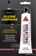


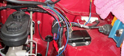
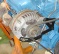
